Digital Dream Standalone Motion Controller DDCS-Expert Users Manual
Page-32
GND1
TXD1
GND2
TXD2
RXD2
RXD1 Serial port 1 Receiver
Serial port 1 Sender
Serial port 1 Ground
Serial port 2 Receiver
Serial port 2 Sender
Serial port level is 232
Serial port level is 232
Serial port 2 Ground
2
3
4
5
6
7
8
9
1
Pin No. Definition NotesMark
4.7 Series Port Wiring
Figure 4-26 Series Ports wiring
Note: It you want to use the single-terminal MPG ( there is no A-B-MPG ), please refer to
Figure 4-25 for reference. As for the unlisted MPG, please take the differential MPG wiring mode.
Series Port is for Modbus extension, it helps to extend with IO card,or the communication
with PLC. If some users need it please contact factory and we will guide you for it.
B-
A-
B+
A+
A+ Green
0V Black
B+ White
0V Black
DDCS Wiring Pin Mark MPG Pin Mark and Color
Figure 4-25 DDCS Expert Wiring with Single-terminal MPG
1
5
6
9
GND
GND
T XD2
RXD2
T XD1
RXD1
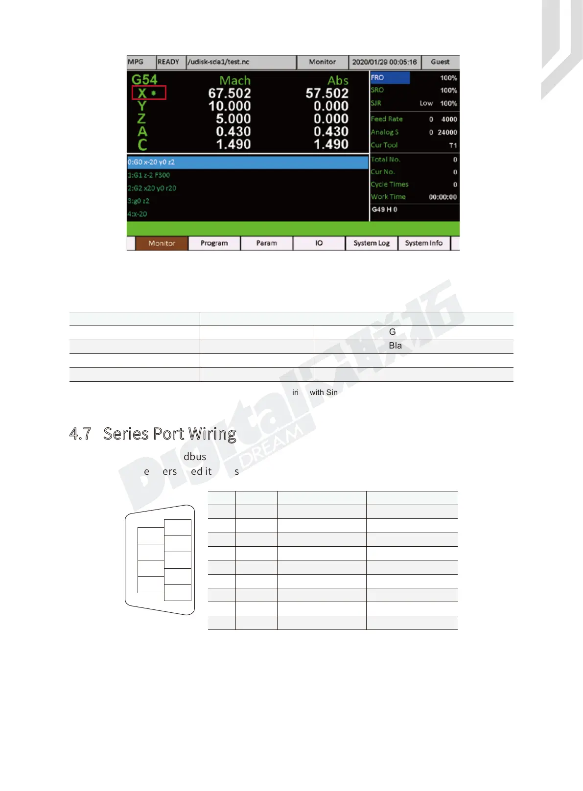
Figure 4-24 The MPG channel is on X axis