Digital Dream Standalone Motion Controller DDCS-Expert Users ManualPage-29
4.6 External Buttons
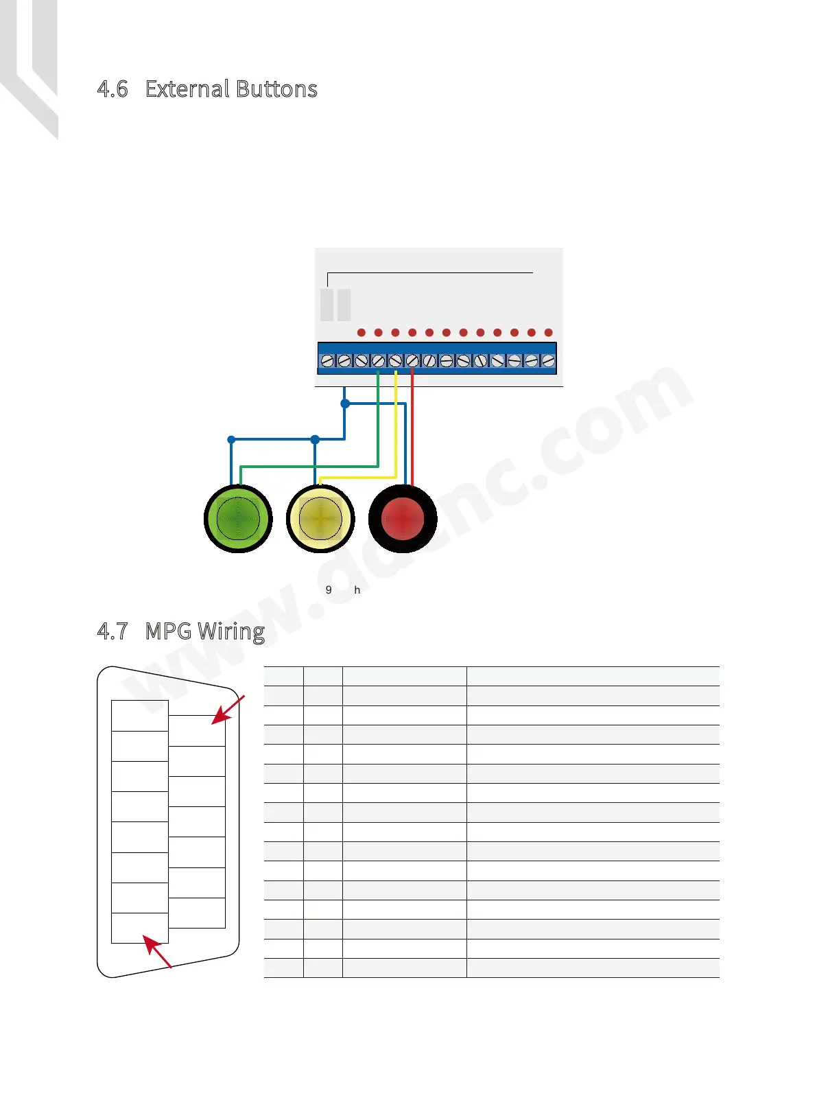
DDCSE Input and Output are the user-defined IO ports, In our example, we already set IN23
as the “ External Start ” input port, IN22 as the “ External Pause ” input port, and IN21 as “ Exter-
nal Stop ” input Port.
Please choose the external buttons which is 24VDC Power supply input. Then no need an
external power supply for them.
Figure 4-19 The wiring methods of External buttons
*** Never short connect the COM- and GND ***
4.7 MPG Wiring
Figure 4-20 MPG wiring table
A-
B-
EP
15
9
8
YIN
4
X10
A+
B+
XIN
ZIN
X100
5
1
GND
5V
COM-
5
X10
X100
XIN
YIN
ZIN
4
B+
B-
A+
A-
COM-
+5V
EP
GND
7
14
6
4
12
5
13
3
11
2
10
8
1
15
9
X100 Ratio
Select X Axis
Select Z Axis
Encoder B Phase -
Encoder A Phase -
Encoder B Phase +
Encoder A Phase +
Input signal COMMON
Ground
X10 Ratio
Select Y Axis
Select 4th Axis
Select 5th Axis
ESTOP Input
Power Supply +
Pin No. Definition Notes
MPG power supply ground
Connect with GND,then Z axis is selected
Connect with GND,then 5th axis is selected
Connect with GND,then X axis is selected
Connect with GND,then Y axis is selected
Connect with GND,then the 4th axis is selected
Connect with GND,then Estop is active
MPG Power supply input positive terminal
MPG B differential input positive terminal
MPG A phase differential input positive terminal
MPG B differential input negative terminal
MPG A phase differential input negative terminal
The switch signal common trenimal.
Mark
Connect with GND, then X100 ratio is selected
Connect with GND, then X10 ratio is selected
START Pause Reset
External Buttons
COM+
COM-
IN24
IN23
IN22
IN21
IN20
IN19
IN18
IN17
IN16
IN15
IN14
IN13
INPUT