DOBOT CR5 User Guide 3 Electrical Specifications
Issue V3.5.3.1 (2020-05-09) User Guide Copyright © Yuejiang Technology Co., Ltd
31
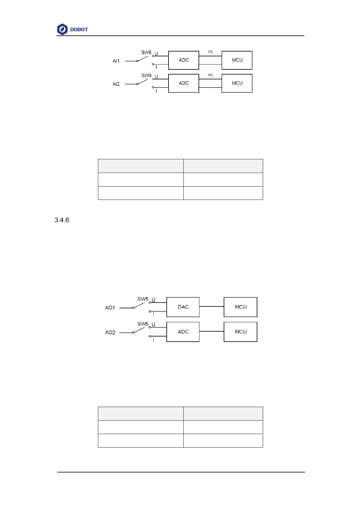
Figure 3.8 Simple analog input circuit
Table 3.10 lists the relation between the DIP switch and analog input.
Table 3.10 The relation between the DIP switch and analog input
Analog Output
3.4.6.1 Introduction
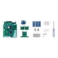
Much like the analog input, an analog output can be set to a current output or voltage output
by the DIP switch. A controller uses 2-channel DIP switches to control 2 channel analog outputs.
Each channel can be controlled separately. Figure 3.9 shows the simple analog output circuit. V
indicates the voltage output and I indicates the current output. The default is voltage output. If you
need to change, please contact our technical support.
Figure 3.9 Simple analog output circuit
Table 3.11 lists the relation between the DIP switch and analog output.
Table 3.11 The relation between the DIP switch status and analog output