Setup
Operating Instructions 867-M PREMIUM - 00.0 - 02/201546
7.2 Removing the transport locks
All transport securing devices must be removed prior to setup.
1. Remove the lashing straps and wooden blocks from the
machine head, the table, and the frame.
2. Remove the support wedges between the machine arm and
throat plate.
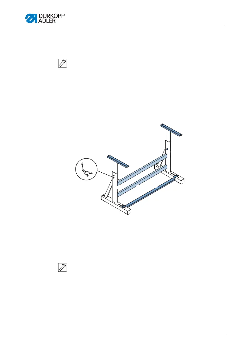
7.3 Assembling frame components
Fig. 25: Assembling frame components
1. Screw the cross bar(s)* (4) onto the frame bars (3).
2. Screw the oil can holder (8) at the rear to the upper cross
bar (4).
3. Screw the cross strut (6) to the foot struts (5).
4. Insert the inner bars (2) in such a way that the longer end of
the head section (1) is above the longer end of the foot struts
(5).
5. Screw the inner bars (2) down so that both head sections (1)
are at the same height.
1
2
3
4
4
5
6
5
7
3
2
1
8
(1) - Head sections of the inner bars
(2) - Inner bars
(3) - Frame bars
(4) - Cross bar(s)*
(5) - Frame foot struts
(6) - Cross strut
(7) - Adjusting screw
(8) - Oil can holder

 Loading...