6. Function blocks
6.1 Manufacturer function blocks
A
B
t
1
+ t
2
= t
s
t
s
C
1
2
4
3
t
s
D
t
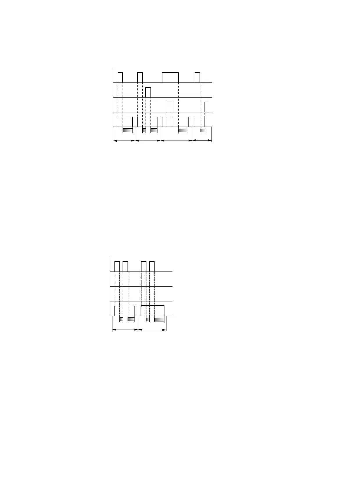
Fig. 146: Signal diagram of timing relay, off-delayed (with/without random switching, with/without ret-
riggering)
1: Trigger coil T..EN
2: Stop coil T..ST
3: Reset coil T..RE
4: Switching contact (N/O contact) T…Q1
ts: Setpoint time.
Range A: The time elapses after the trigger coil is deactivated.
Range B: The Stop coil stops the time from elapsing.
Range C: The Reset coil resets the relay and the contact.
After the reset coil drops out, the relay continues to work normally.
Range D: The Reset coil resets the relay and the contact when the function block is timing out.
Fig. 147: Signal diagram of timing relay, off-delayed (with/without random switching, with/without ret-
riggering)
Range E: The trigger coil drops out twice.
The set time ts consists of t1 plus t2 (switch function not retriggerable).
Range F: The trigger coil drops out twice. The actual time t1 is cleared and the set time ts elapses com-
pletely (retriggerable switch function).
How the timing relay works with the on/off-delayed operating mode with and
without random times
Time value I1: on-delay time
Time value I2: Off-delay time
Random switching
easyE402/24 MN050009ENEaton.com
279