10. easyE4 communication Connection to other devices
10.16 easy communication modules
To install a Modbus RTU communication system, follow the steps below in the spe-
cified order:
1. Install the module mechanically and connect it to the easyE4 base device
2. Connect the Modbus RTU signal cables to the connection terminals on the EASY-
COM-RTU-… module
3. Connection of power supply
4. Configure the EASY-COM-RTU-… module in easySoft 8
Please note that the EASY-COM-RTU-… connection can only be configured with
easySoft 8.
See also
→ " Installation position", page 54
→ "Mounting", page 58
and
→ "Connection terminals", page 66
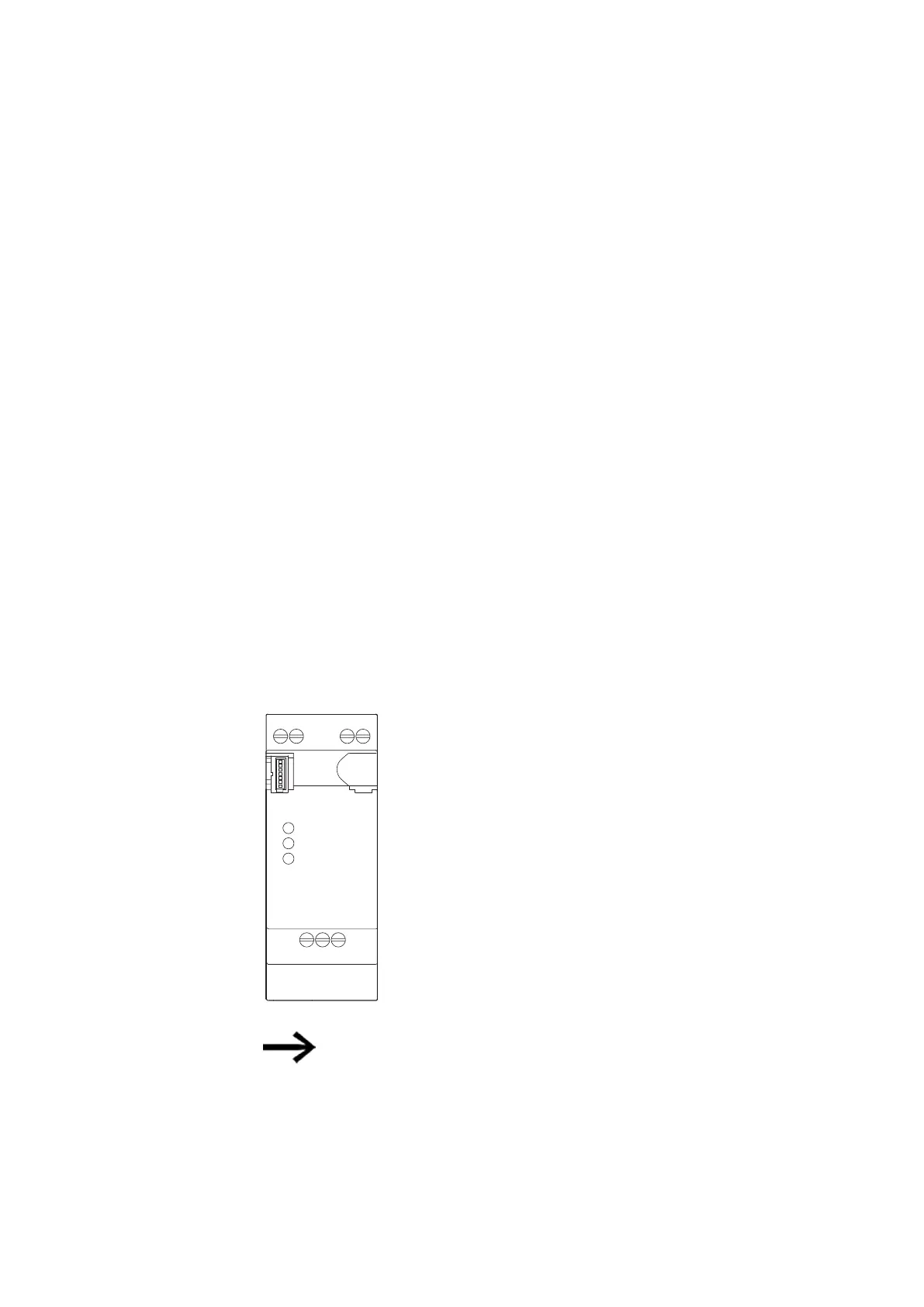
Connecting the Modbus RTU signal cables
Terminal layout
The EASY-COM-RTU-… module features an RS-485 interface that is galvanically isol-
ated from the power supply (POW).
Config
Modbus R
TU
POW / RUN
+24 V
P
O
W
0 V
+24 V
0 V
P
O
W
COM B+ A-
Description
POW
+24 V
Supply voltage +24 V
0V
Supply voltage 0 V
RS-485
COM
Modbus RTU Common
B+
Modbus RTU + (D1*)
Amp
Modbus RTU - (D0*)
Tab. 133: Terminal assignment EASY-COM-RTU-…
* D1 and DO are the designators in conformity with modbus.org as
defined in the following documents:
l
MODBUS over serial line specification and implementation guide
l
MODBUS application protocol specification
768
easyE402/24 MN050009ENEaton.com