Servicing the EMP – 225
•
•
•
•
•
•
•
•
•
•
•
•
•
•
6.3.5 Connecting an external contact device
To connect an external device to the EMP:
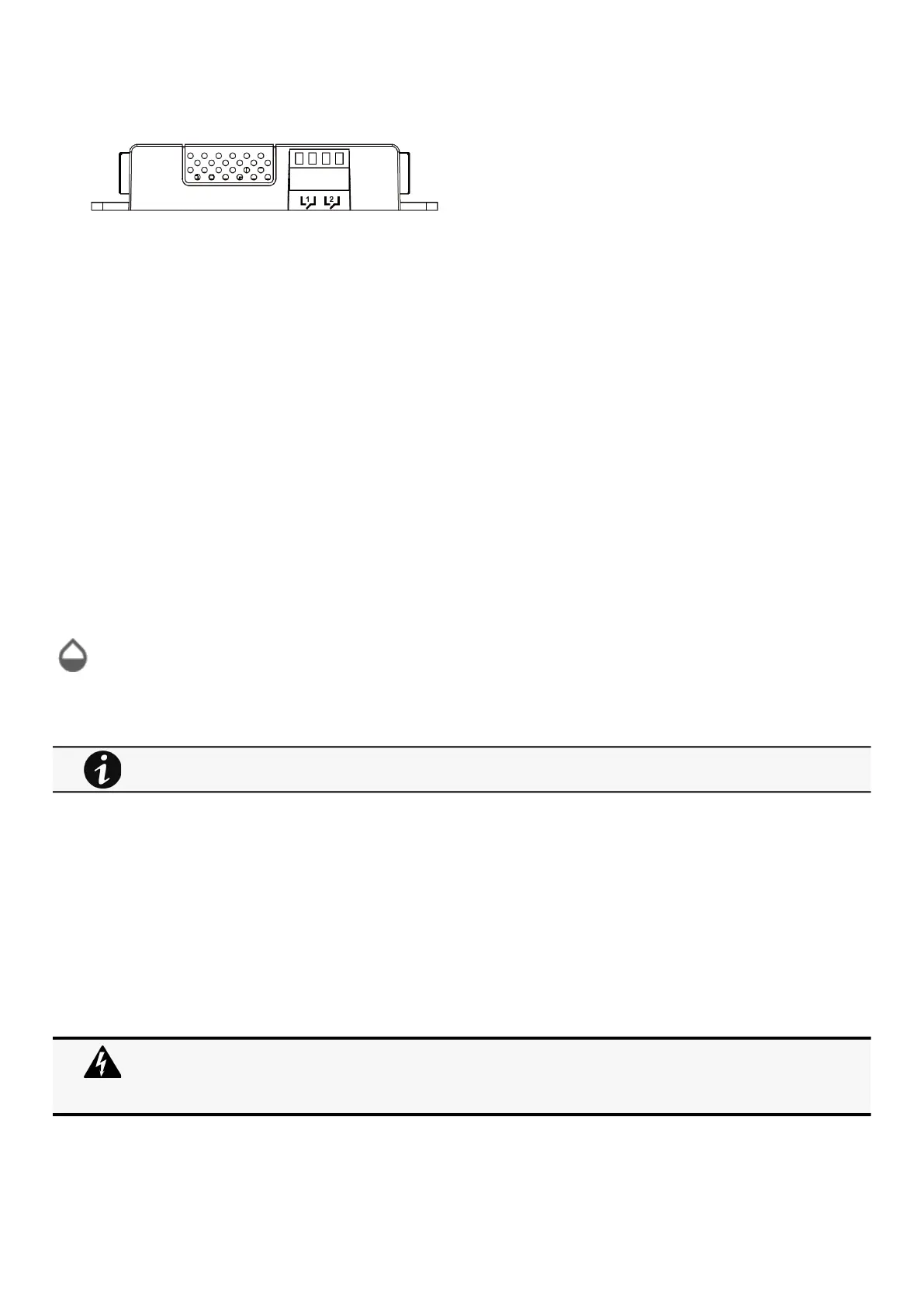
STEP 1 –Connect the external contact closure inputs to the terminal block on the EMP (see the table and the figure below):
External contact device 1. Connect the return and signal input wires from device 1 to screw terminals 1.
External contact device 2. Connect the return and signal input wires from device 2 to screw terminals 2.
STEP 2 –Tighten the corresponding tightening screws on top of the EMP to secure the wires.
6.4 Commissioning the EMP
6.4.1 On the Network Module device
STEP 1–Connect to the Network Module
On a network computer, launch a supported web browser. The browser window appears.
In the Address/Location field, enter:https://xxx.xxx.xxx.xxx/where xxx.xxx.xxx.xxx is the IP address of the Network Module.
The log in screen appears.
Enter the user name in the User Name field.
Enter the password in the Password field.
ClickLogin. The Network Module web interface appears.
STEP 2–Navigate to Environment menu:
STEP 3– Proceed to the commissioning, refer to the contextual help for details.
ClickDiscover. The EMP connected to the Network module appears in the table.
Press the pen logoto edit EMP information and access its settings.
ClickDefine offsetsto define temperature or humidity offsets if needed.
STEP 4– Define alarm configuration, refer to the contextual help for details.
Select theAlarm configurationpage.
Enable or disable alarms.
Define thresholds, hysteresis and severity of temperature, humidity and dry contacts alarms.
6.5 Using the EMP for temperature compensated battery charging
This section applies only to UPS that provides temperature compensated battery charging option.
When discovered, the orange LEDs of the EMP RJ45 connectors shows the data traffic.
If the discovery process fails refer to the troubleshooting section.
Address must be defined before EMP power-up; otherwise, the changes will not be applied.
Do not set Modbus address to 0;otherwise, the EMP will not be detected.
Definea unique addressfor all the EMPs in the daisy-chain.
Set the RS485 termination (TER) to 1 on the last EMP of the daisy chain. On other EMPs this should be set to 0.