2 Engineering
2.7 Braking resistances
DC1 Variable Frequency Drive 04/16 MN04020003Z-EN www.eaton.com 45
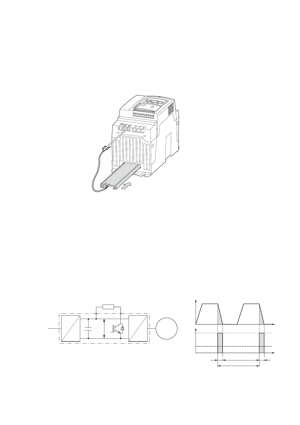
In the case of units with a frame size of FS2 or FS3, brake resistor
DX-BR3-100 (P
D
= 200 W) can be inserted underneath the heat sink.
In addition, parameter P-34 must be set to a value of 1 in order to protect
against thermal overloads (braking chopper activated with electronic overload
protection).
Figure 15: DC1 variable frequency drive with a frame size of FS2 and a DX-BR3-100
brake resistor
It is often difficult to specify a suitable brake resistor for specific applications.
This is due to the fact that not all of the application conditions required for
sizing will be available when the engineering stage starts. Because of this,
and as a simplification, brake resistors are instead usually classified for two
load groups:
• Low duty: Low load with short braking duration and low duty factor
(up to about 25 %), e.g., for horizontal conveyors and handling
equipment for bulk cargo and general cargo, end carriages, sliding doors,
and turbomachinery (centrifugal pumps, fans).
• High duty: High load with long braking duration and high duty factor
(at least 30 %), e.g., for elevators, downhill conveyors, winders,
centrifuges, flywheel motors, and large fans.
Figure 16: Braking cycle, fast motor stop with external brake resistor

 Loading...


