3 Installation
3.6 Electrical Installation
86 DC1 Variable Frequency Drive 04/16 MN04020003Z-EN www.eaton.com
3.6.2 Connection on control section
The connection to the control section is made using the plug-in connection
terminals:
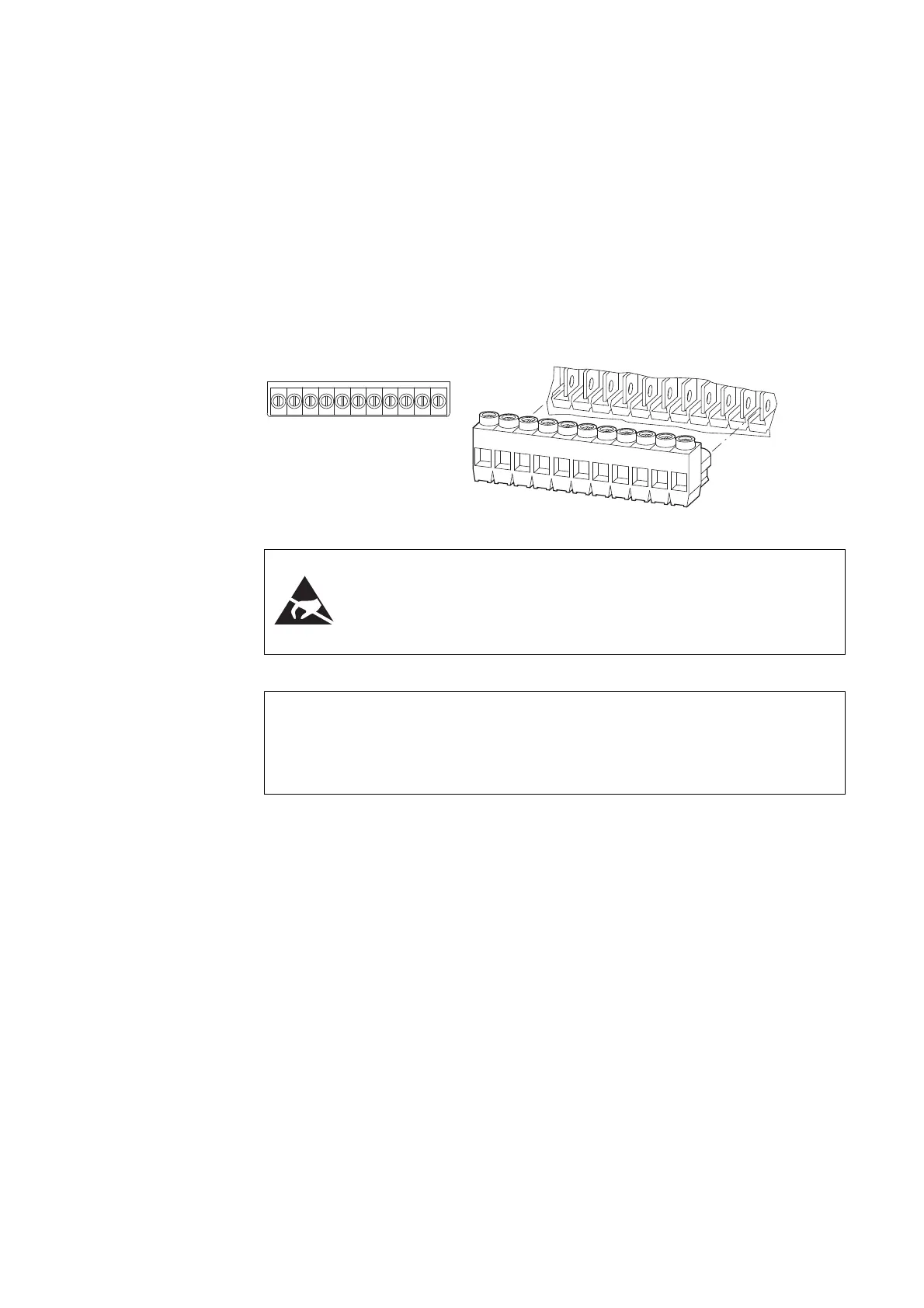
• Terminals 1, 5, 7, 9: for the internal power supply
• Terminals 2, 3, 4, 6: for digital and analog input signals
• Terminal 8: for a digital or analog output signal
• Terminals 10, 11: for a potential-free relay output
Figure 51: Control signal terminal layout and factory designations
ESD measures
Discharge yourself on a grounded surface before touching the
control terminals and the circuit board to prevent damage
through electrostatic discharge.
DANGER
Before touching or handling the wired control signal terminals,
check to make sure that the terminals (terminals 10 and 11) are
de-energized.
→
The relay contact (terminals 10, 11) may be wired to a higher-
level control circuit that has a dangerous voltage (e.g., 110 V AC,
230 V AC) even when the variable frequency drive is de-
energized.
→
When using more than one control voltage, we recommend
using separate cables.
Example
24 V DC at control signal terminals 1, 2, 3, 4, 6, and 8 and
110 or 230 V AC at control signal terminals 10 and 11.

 Loading...


