3 Installation
3.6 Electrical Installation
DC1 Variable Frequency Drive 04/16 MN04020003Z-EN www.eaton.com 85
Table 9: Cable glands that can be used (figures 47, 48)
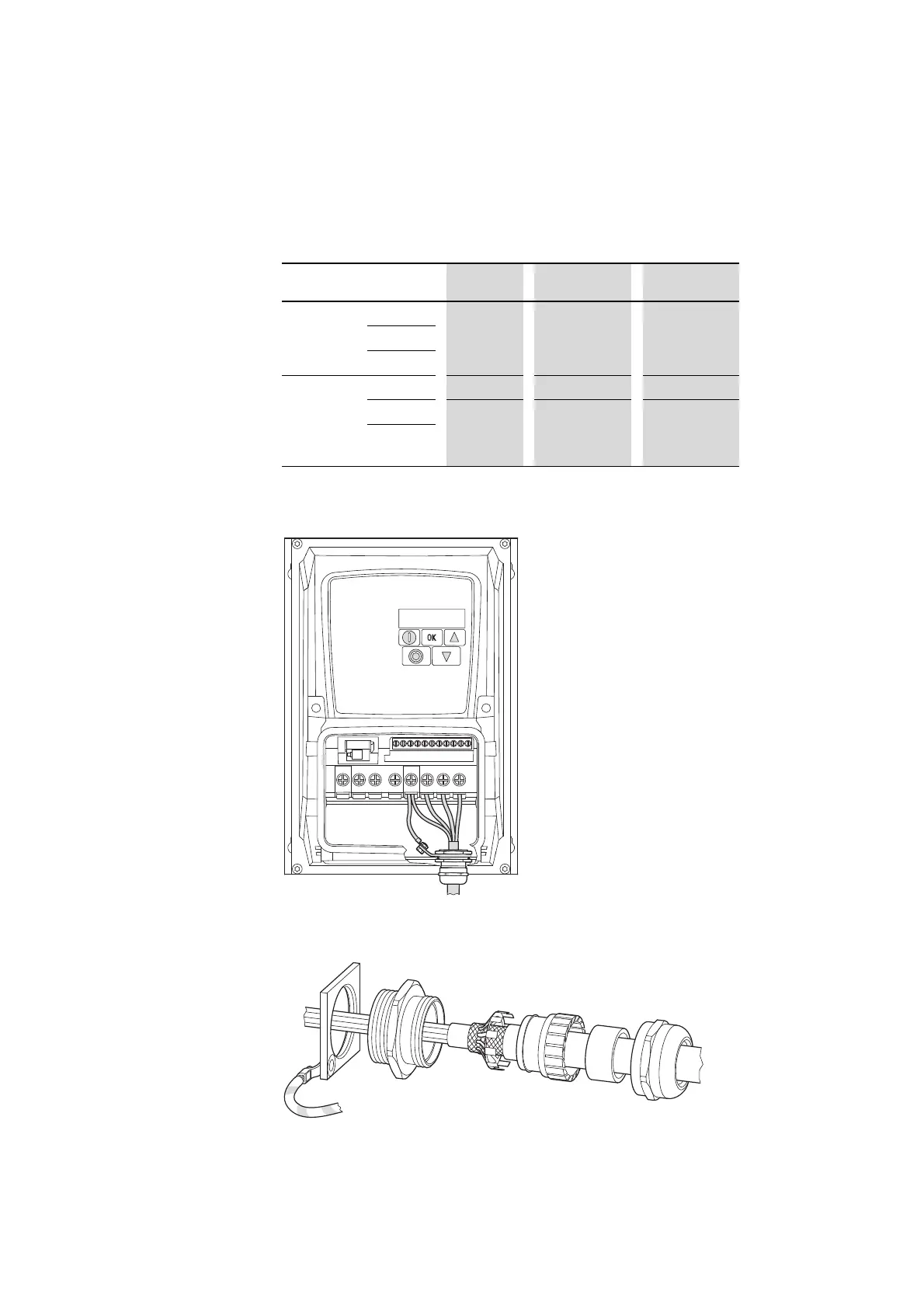
The EMC cable gland must be earthed properly – e.g., with a metal lock nut
that is then connected to the PE terminal.
Figure 49: Grounding the EMC cable gland
Figure 50: Example: diagram of EMC gland assembly
→
Make sure that the cable glands have at least an IP66 degree of
protection.
Range Size
Hole size PG-gland Metric gland
Control
section
Control
FS1
2 x 22 mm 2 x PG 13.5
1 x PG 16
2 x M20
1 x M25
FS2
FS3
Power
section
Mains
Motor
FS1
3 x 22 mm 3 x PG 13.5 3 x M20
FS2
1 x 22 mm
2 x 25 mm
1 x PG 13.5
2 x PG 16
1 x M20
2 x M25
FS3

 Loading...


