7 Accessories
7.1 Device-specific accessories
170 DC1 Variable Frequency Drive 04/16 MN04020003Z-EN www.eaton.com
7.1.4 DXC-EXT-LOCSIM simulator
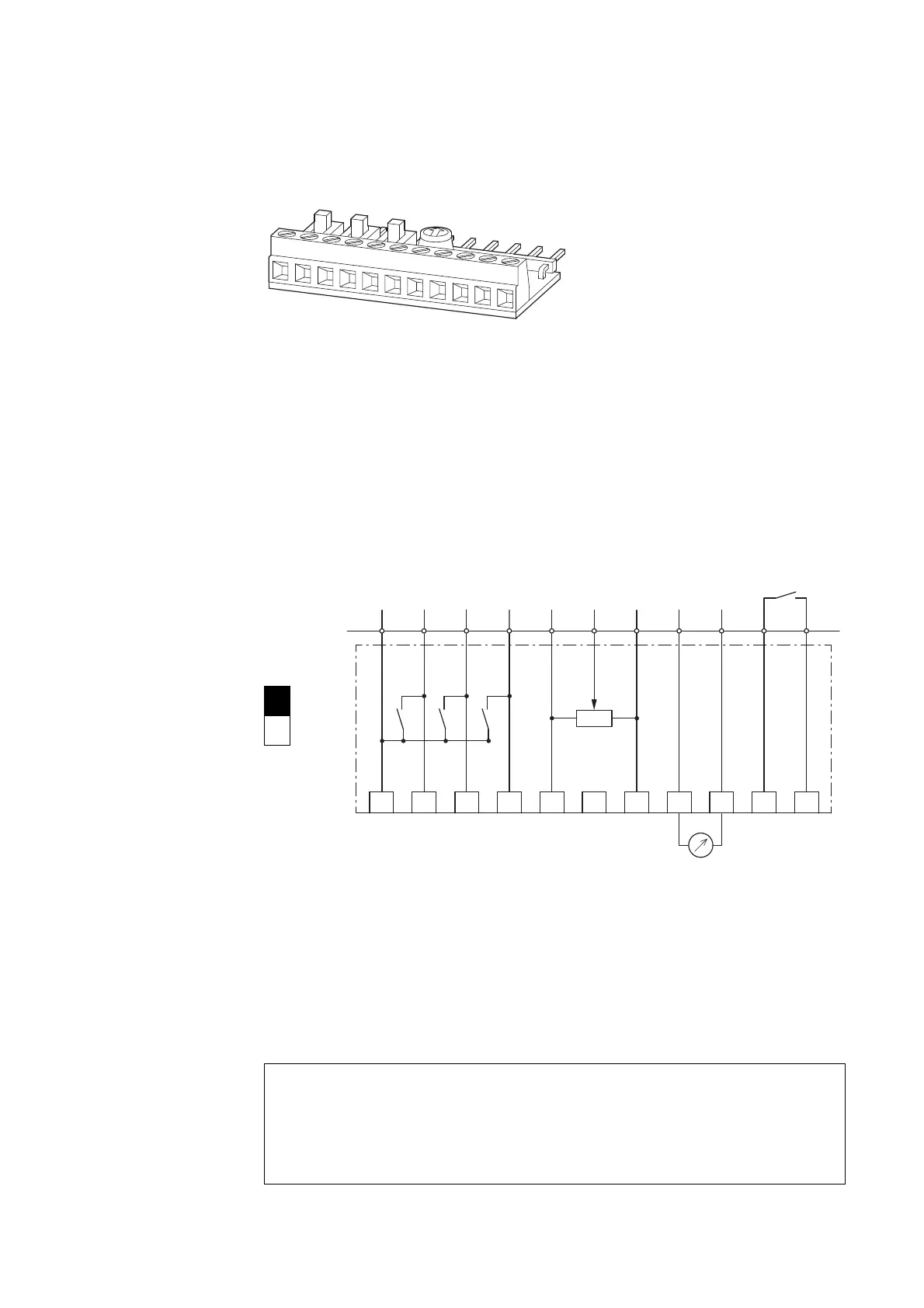
Figure 92: DXC-EXT-LOCSIM
DXC-EXT-LOCSIM is a simple commissioning and test simulator for DC1
variable frequency drives.
Three microswitches and a PCB mount potentiometer make it possible to
easily put the variable frequency drive into operation “out of the box” based
on the corresponding help cards when using the drive’s default settings
Section “4.6 Help leaflets”, page 122.
Figure 93: Block diagram DXC-EXT-LOCSIM simulator
The three microswitches can be used to directly drive (from left to right) the
three digital inputs DI1, DI2, and DI3 with the internal control voltage
(24 V DC). Meanwhile, the POTI PCB mount potentiometer can be turned
clockwise to sets the frequency reference value (0 - 50 Hz).
The analog output signal from AO (0 - 10 V DC) will be available at control
signal terminals 8 and 9 as per the output frequency (0 - 50 Hz).
→
For detailed instructions on how to install the module, please
refer to instruction leaflet IL04012019Z.
1 = OFF
0 = ON
NOTICE
Manual operation!
As per IEC 60449, only extra-low voltage should be connected
to internal relay K1 via control signal terminals 10 and 11
( 50 V AC, 120 V DC).
1 2 3 4 5 6 7 8 9 10 11
2
DI1
3
DI2
4
DI3
1
5
+10 V/
20 mA
6
POTI
7
0 V
8
AO
0 ... +10 V/
20 mA
9
0 V
10 11
1DC1 2 3 4 5 6 8 9 10 11
P-18 = 1
RUN
7
+
K1
≦ 24 V
AI
0 ... +10 V

 Loading...


