3 Installation
3.6 Electrical Installation
88 DC1 Variable Frequency Drive 04/16 MN04020003Z-EN www.eaton.com
3.6.2.3 Connection example
Figure 52: Simple connection example
• Two operating directions:
• FWD = clockwise rotating field
• REV = anticlockwise rotating field
• R1: External reference value potentiometer, frequency reference value
0- f
max
(P-01)
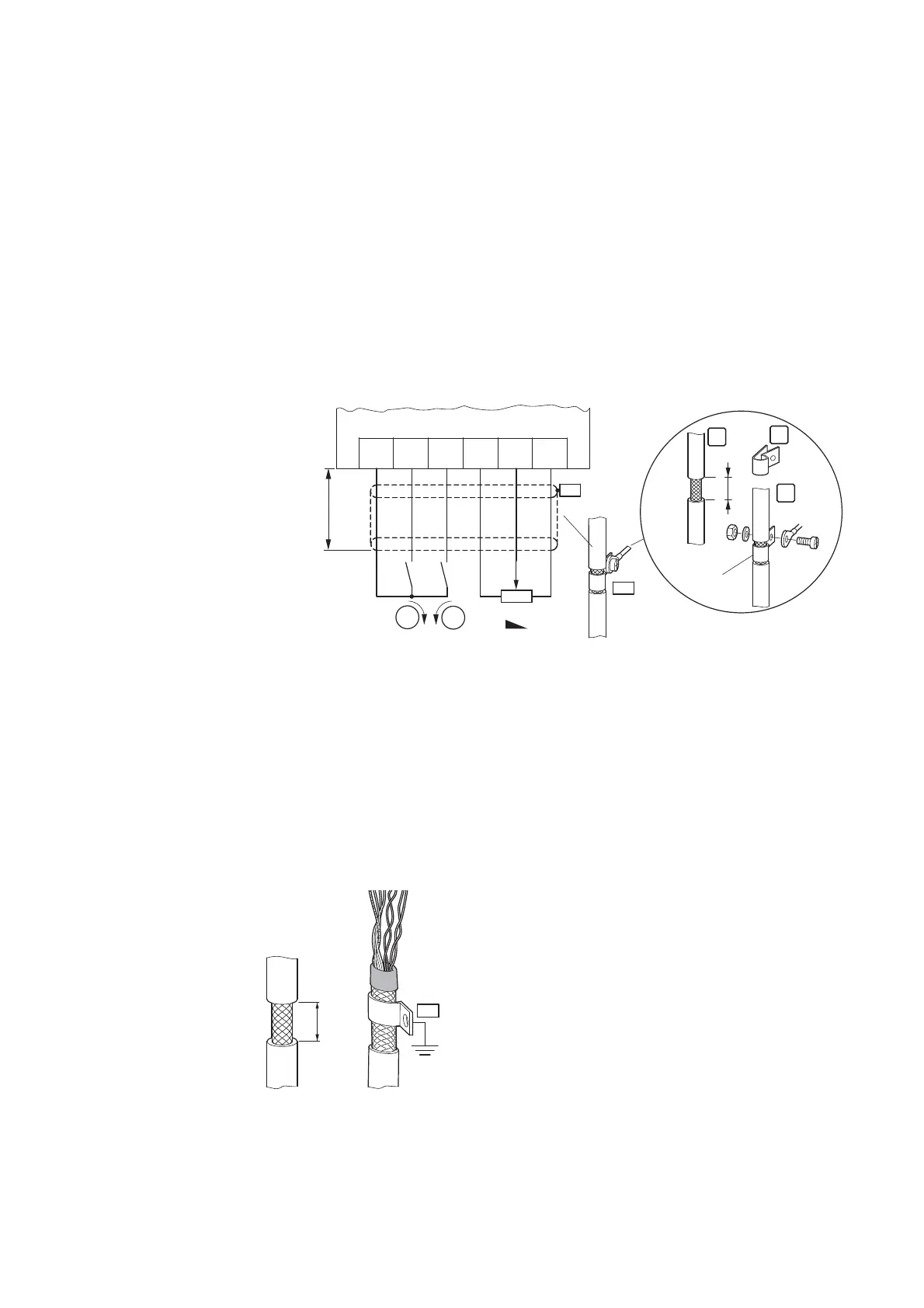
The control cables should be screened and twisted for the external
connection. The screening is applied on one side in the proximity of the
variable frequency drive (PES).
Figure 53: Screen termination at one end (PES) close to the variable frequency drive
→
The control terminals’ functions and electrical parameters can
be changed with
• Parameter,
• Expansion modules DXC-EXT-…
( Section 7.1.2, “DXC-EXT-2RO output expansion“,
page 166 and Section 7.1.3, “DXC-EXT-2RO1AO output
expansion“, page 168).

 Loading...


