© Edwards Limited 2015. All rights reserved. Page 43
Edwards and the Edwards logo are trademarks of Edwards Limited.
Operation
M588-00-880 Issue E
4.2 Status indicators
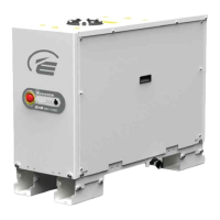
The GXS dry pumping system has a number of LEDs that indicate pump status. The status LEDs are found on the front
panel controls, refer to Figure 1 and also on the rear panel, refer to Figure 3.
Table 18 - Start, warm-up and on-process sequences
Sequence Description
Start pump Shaft Seal Purge (SSP) valve opened.
Pump runs.
Warm-up Pump runs at 110 Hz until it reaches working temperature and then goes on-process
[default auto on-process].
On-process Inlet isolation valve opened (if fitted).
Pump speed from standby (Green Mode) to full speed may be ramped by
configurable increments instead of going straight to full speed.
Pump will not go on-process if there are active warnings.
Pump may be configured to ignore warnings and go straight onto process.
Gas ballast is opened (if fitted, medium duty pumps only).
Table 19 - Status indicator LEDs
Indicator Name LED colour Location Meaning
Power Green Front panel
(Figure 1, item 7) and Rear
panel (Figure 3, item 4)
Illuminates continuously when the system has
power.
Front Panel Control Green Front panel
(Figure 1, item 6)
Illuminates continuously to indicate the front
panel is 'in control'.
Tool Control Green Rear panel (Figure 3, item 9) Illuminates continuously to indicate the MCM
MicroTIM is 'in control'.
Pump Running Green Front panel
(Figure 1, item 2) and Rear
panel (Figure 3, item 7)
Illuminates continuously when the pump is
running on-process.
Flashes to indicate the pump is warming up,
shutting down or in Green Mode/Standby mode.
Refer to Section 4.2.1.
Green Mode/
Standby
Green Front panel
(Figure 1, item 10)
Illuminates continuously when pump is in Green
Mode/Standby mode.
Flashes to indicate the pump is warming up,
refer to Section 4.2.1.
Warning Yellow Front panel
(Figure 1, item 8) and Rear
panel (Figure 3, item 6)
Illuminates continuously to indicate a pump
warning.
Flashes to indicate an internal communication
problem, refer to Appendix A3.5.1.
Alarm Red Front panel
(Figure 1, item 9) and Rear
panel (Figure 3, item 7)
Illuminates continuously to indicate a pump
alarm.
Flashes to indicate an internal communication
problem, refer to Appendix A3.5.1.
Ethernet LAN Green Rear panel (Figure 3, item 1) Flashes to indicate that there is network traffic
and Ethernet packets are being received.
Ethernet Link Yellow Rear panel (Figure 3, item 2) Illuminates continuously to indicate that an
Ethernet protocol is active.

 Loading...


