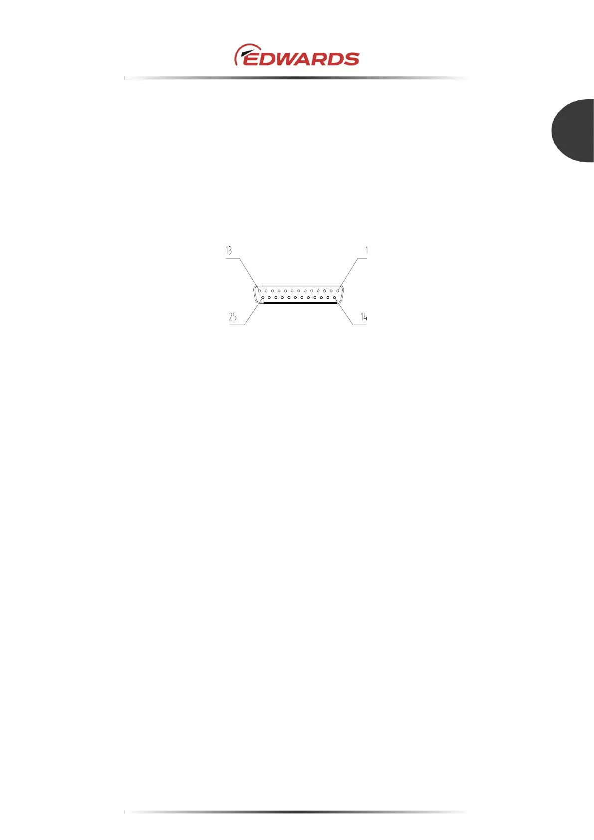
4.9 Parallel port input/output signal
The remote input/output signal connector "X2 REMOTE" is used for input/output remote signals (see
Figure 31). This connector is of D-Sub (25 pins, socket type) type. The screw for connector is M2.6.
Note: The connector (pin type) is not included. Procure control equipment at your company.
Note: It is recommended to use a remote cable with shield type, and conduct both ends grounding
(Electromagnetic shielding) or single point grounding (Electrostatic shield). (see Section
5.2.6)
Figure 31 - X2 REMOTE connector
4.9.1 Input signal pins
When using contact input, refer to Table 12 and Figure 32. The input signal pins function only when
the input operation port is set to the parallel port.
Two abbreviations are used in Table 12 and Figure 32:
COM: Common Pin
IN: Input Pin
When performing remote operation using a photo-coupler, consider the variation in the current
transfer characteristics of the photo-coupler. And, check notes indicated in the data sheet.

 Loading...