Control Unit IV Reference Manual
529-0004 Ver.3 B-1
B. CABLE ASSEMBLIES
This appendix covers the pin assignment on the cable assemblies that come with the Control
Unit. It also shows the pinout of the Control Unit’s three communication ports and its
backup port. Refer to the tables in each section for a description of the signals and the
direction of the signal flow. Note that no signal is specified for any unused pins.
B.1 Pinout on COM ports
B.1.1 Pinout for COM 1 and COM 2 ports
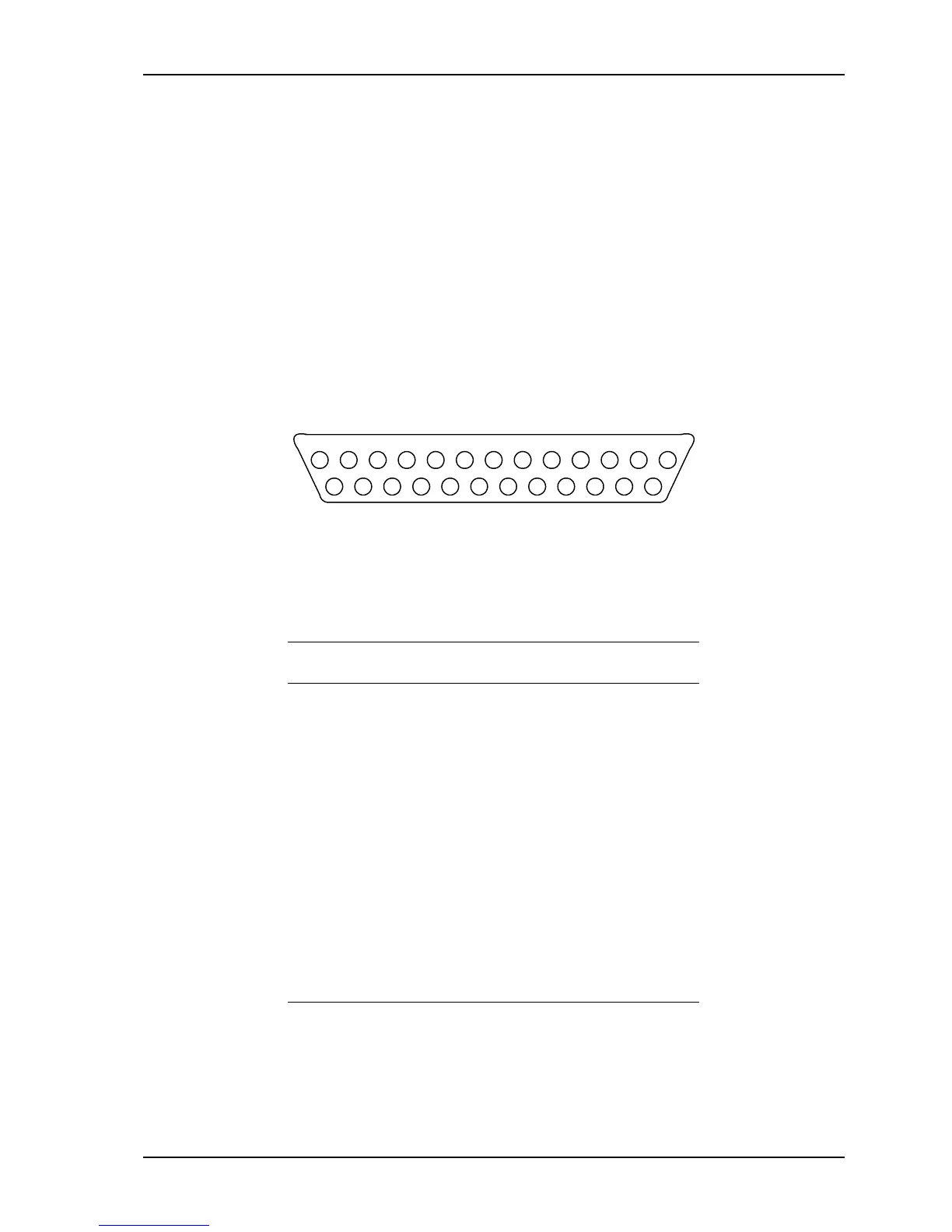
Pin 1 is the rightmost pin on the top row of the female connector. The pins are numbered
from right to left and from top to bottom, in accordance with the standard numbering system
for female connectors.
13121110987654321
25 24 23 22 21 20 19 18 17 16 15 14
Figure B-1: Female DB-25 connector (COM 1 and COM 2)
The following table shows the signal assigned to each pin on the COM 1 and COM 2 ports.
Note that COM 1 and COM 2 are female DB-25 connectors, and are wired as DCE devices.
Table B-1: Pinout on COM 1 and COM 2 (DCE)
Pin Signal Direction
1 Protective ground --
2 Transmitted data (TX) Input
3 Received data (RX) Output
4 Request to send (RTS) Input
5 Clear to send (CTS) Output
6 Data set ready (DSR) Output
7 Signal ground (GND) --
8-19 Not used --
20 Data terminal ready (DTR) Input
21-25 Not used --