Cable Assemblies Control Unit IV Reference Manual
B-4 529-0004 Ver.3
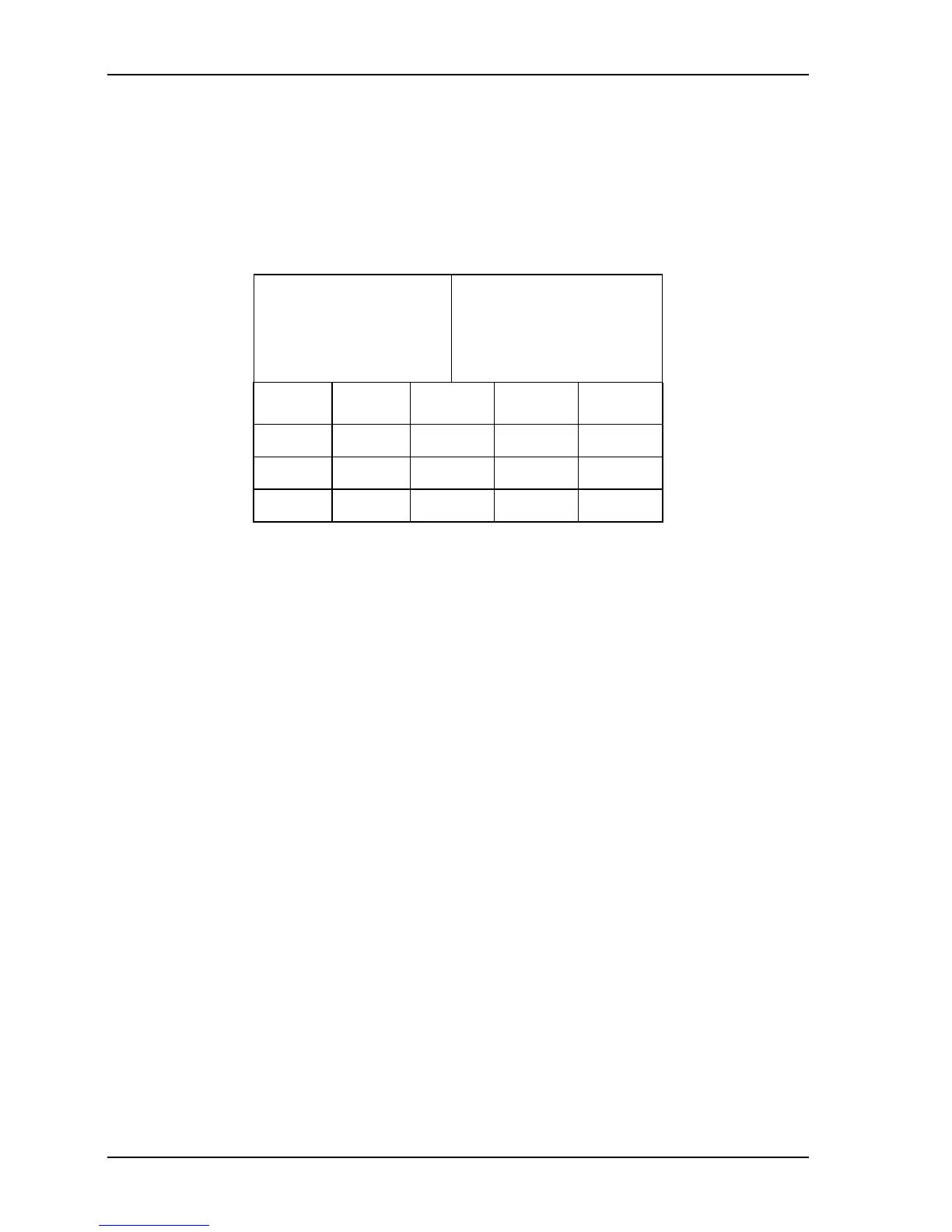
RS-232 cable with 9-pin connectors
Note that COM 3 is a female DB-9 connector, wired as a DCE device. If a DTE device such
as a computer is connected to this port, use an RS-232 cable to ensure that the signals shown
in Table B-4 are assigned to the correct pins. If another DCE device is connected to this port,
you must use a null modem cable with DB-9 connectors (see section B.2.2).
Table B-4: RS-232 cable with male and female DB-9 connectors
Male DB-9, to be
connected to the
Control Unit’s
COM 3 (DCE)
Female DB-9, to be
connected to the host
computer’s port (DTE)
Flow Pin Signal Pin Flow
Output
2 RX 2
Input
Input
3 TX 3
Output
--
5 Ground 5
--
Pins 1, 4 and 6-9 are not used. Note that if you use a cable with only three wires (pins 2,
3 and 5), then you will not be able to use hardware flow control on the connection.