Control Unit IV Reference Manual Cable Assemblies
529-0004 Ver.3 B-5
B.2.2 Cable between the Control Unit and a modem (DCE to DCE)
This section covers the null modem cable assemblies used with the Control Unit. These
cables are used to ensure communication between two DCE devices, i.e. the Control Unit
and another DCE device such as a modem or another Control Unit. The cables are made with
crossover wires to ensure signal transmission and reception. If you do not require a null
modem cable, see section B.2.1.
In a redundancy system, you must use a null modem cable on COM 2 in order to connect the
two Control Units to each other. This cable, with DB-25 connectors, is provided by
Electroline and is used to synchronize the two units.
Null modem cable with 25-pin connectors (crossover)
Note that COM 1 and COM 2 are female DB-25 connectors, wired as DCE devices. If
another DCE device such as a modem is connected to one of these ports, use a null modem
RS-232 cable to ensure that the signals shown in Table B-5 are assigned to the correct pins.
If you are using this cable to synchronize two units in a redundancy system, you must
connect the cable to the Control Unit’s COM 2 port.
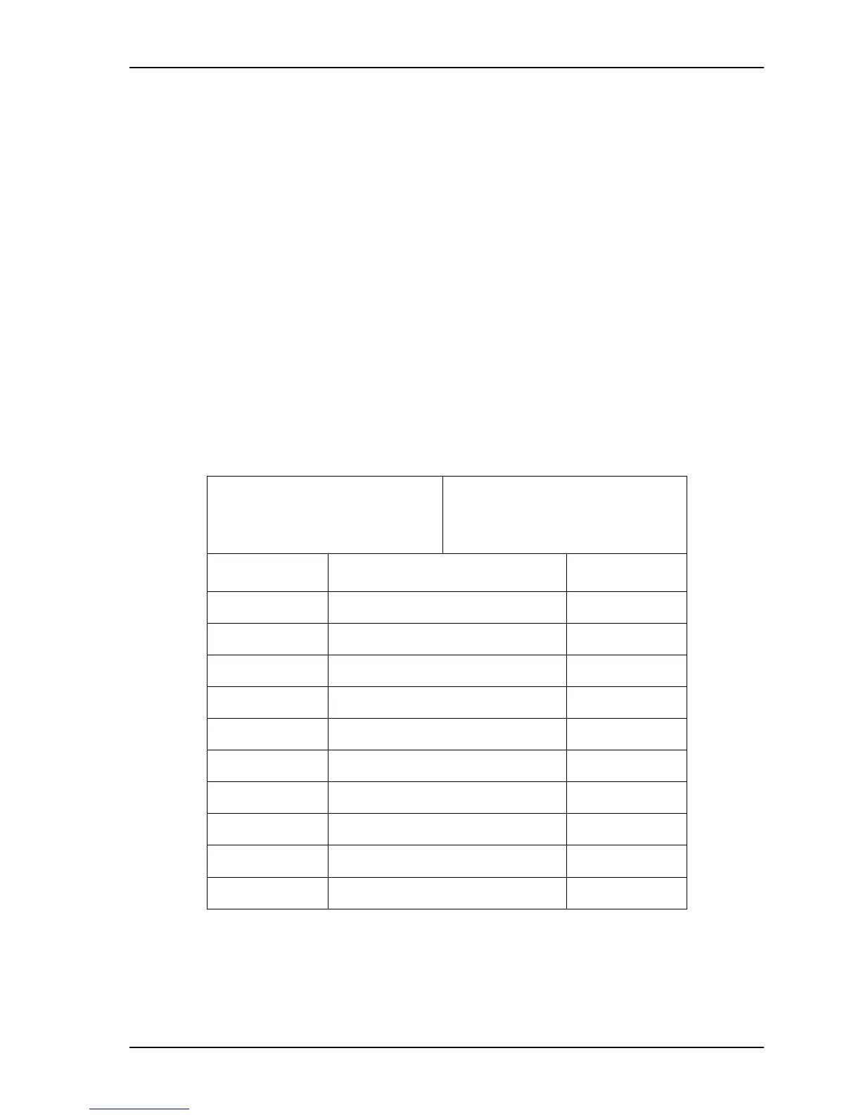
Table B-5: Null modem cable with male DB-25 connectors
Male DB-25, to be connected
to the Control Unit’s COM 1
or COM 2 (DCE)
Male DB-25, to be connected to
the modem’s port or the
Control Unit’s COM 2 (DCE)
Signal (flow) Pins Pins Signal (flow)
GND 1 — 1 GND
TX (input) 2 — 3 RX (output)
RX (output) 3 — 2 TX (input)
RTS (input) 4 — 5 CTS (output)
CTS (output) 5 — 4 RTS (input)
DSR (output) 6 — 20 DTR (input)
GND 7 — 7 GND
CD (output) 8 — 20 DTR (input)
DTR (input) 20 — 6 DSR (output)
DTR (input) 20 — 8 CD (output)
Pins 9-19, 21 and 23-25 are not used. Note that if you use a cable with only three wires
(pins 2, 3 and 7), then you will not be able to use hardware flow control on the
connection.