Control Unit IV Reference Manual Cable Assemblies
529-0004 Ver.3 B-3
B.2 RS-232 cables
B.2.1 Cable between the Control Unit and a host computer (DCE
to DTE)
This section covers the cable assemblies that are used for RS-232 communications between
DCE and DTE devices.
Two RS-232 cables are provided with the Control Unit: one with 25-pin connectors and one
with 9-pin connectors. If you have a redundancy system, a third RS-232 cable is provided;
this cable is a flat cable with 25-pin connectors that is used on COM 1 of the Control Unit.
For all 25-pin connectors on the RS-232 cables, see Table B-3.
RS-232 cable with 25-pin connectors
Note that COM 1 and COM 2 are female DB-25 connectors, wired as DCE devices. If a DTE
device such as a computer is connected to one of these ports, use an RS-232 cable to ensure
that the signals shown in Table B-3 are assigned to the correct pins. If another DCE device is
connected to these ports, you must use a null modem cable (see section B.2.2).
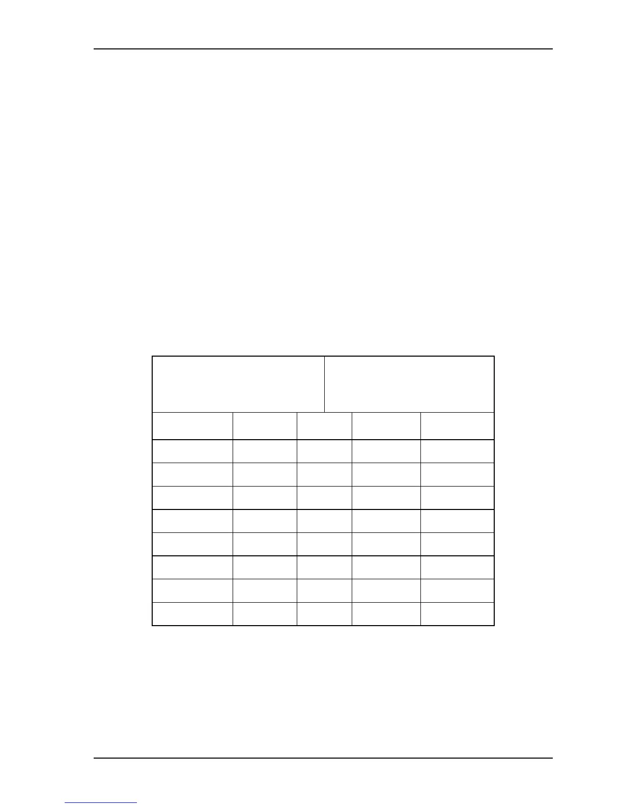
Table B-3: RS-232 cable with male and female DB-25 connectors
Male DB-25, to be connected
to the Control Unit’s COM 1
or COM 2 port (DCE)
Female DB-25, to be
connected to the host
computer’s port (DTE)
Flow Pin Signal Pin Flow
-- 1 GND 1 --
Input 2 TX 2 Output
Output 3 RX 3 Input
Input 4 RTS 4 Output
Output 5 CTS 5 Input
Output 6 DSR 6 Input
-- 7 GND 7 --
Input 20 DTR 20 Output
Pins 8-19 and 21-25 are not used. Note that if you use a cable with only three wires (pins
1, 2 and 7), then you will not be able to use hardware flow control on the connection.