Installation Control Unit IV Reference Manual
2-8 529-0004 Ver.3
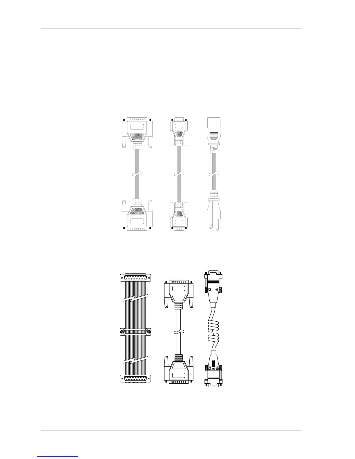
2.6 Cable assemblies and applications
The Control Unit requires various cables, connectors and adapters to interface with a host
computer, peripheral devices and measuring instruments. Figure 2-3 illustrates the main
cables the Control Unit uses whether it is installed alone or with a backup unit. Figure 2-4
shows the cables that are used with a backup unit.
Standard cabling instructions are provided in sections 2.7.1 to 2.7.4. Additional instructions
for redundancy system cabling are provided in section 2.7.5.
(2) RS-232 cables
with 25-pin M-F
connectors
(1) RS-232 cable
with 9-pin M-F
connectors
(1) Three-wire
power cord with
M-F connectors
Figure 2-3: Connection cables for a single Control Unit
(1) 25-pin M-F-M
three-way ribbon
cable
(1) 25-pin M-M
synchronization
cable (null modem)
(1) 9-pin M-M
redundancy
cable
Figure 2-4: Redundancy kit cables