Cable Assemblies Control Unit IV Reference Manual
B-2 529-0004 Ver.3
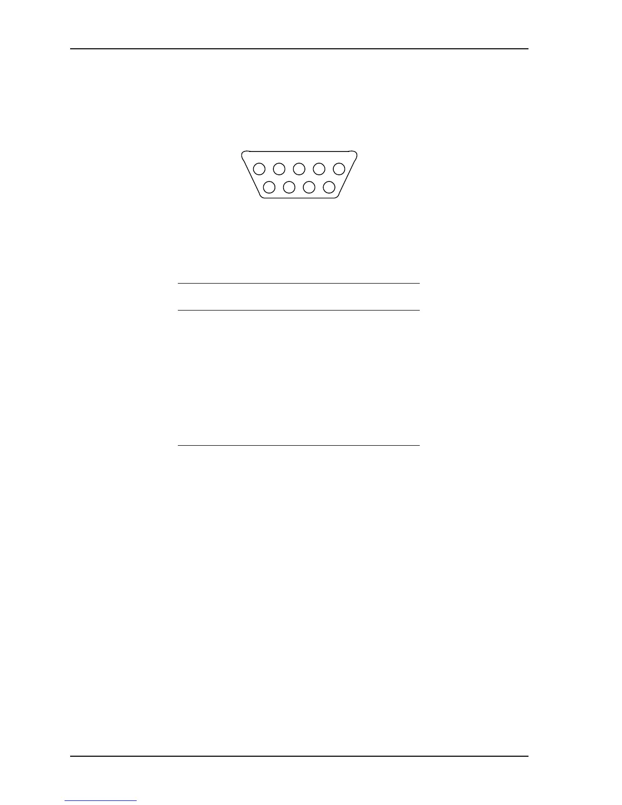
B.1.2 Pinout for COM 3 port
Pin 1 is the rightmost pin on the top row of the female connector. The pins are numbered
from right to left and from top to bottom, in accordance with the standard numbering system
for female connectors.
54321
9876
Figure B-2: Female DB-9 connector (COM 3)
The following table shows the signal assigned to each pin on COM 3. Note that COM 3 is
wired as a DCE device.
Table B-2: Pinout on COM 3
Pin Signal Direction
1 Not used --
2 Receive data (RX) Output
3 Transmit data (TX) Input
4 Not used --
5 Signal ground (GND) --
6-9 Not used --