Control Unit IV Reference Manual Installation
529-0004 Ver.3 2-9
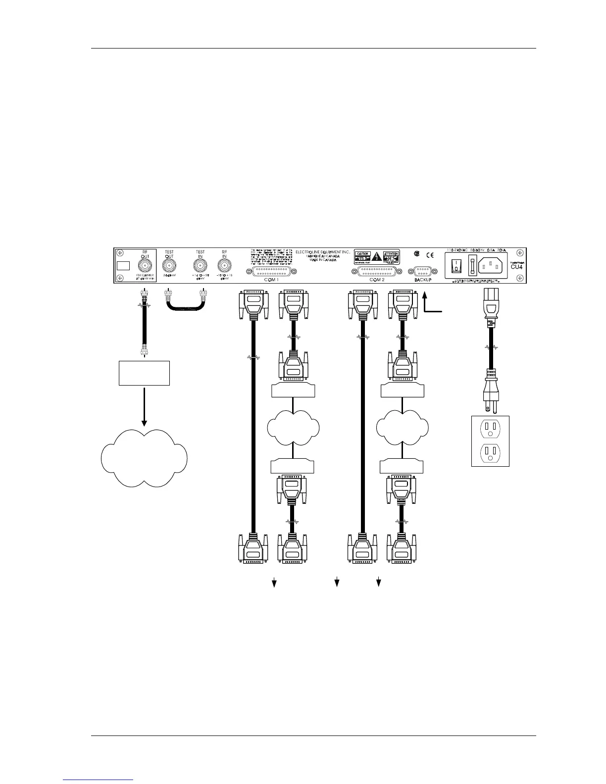
2.7 Connecting the Control Unit
This section covers all the cabling instructions for the Control Unit, whether it is used alone
or used with a backup unit in a redundancy system. Figure 2-5 shows the cabling diagram for
a single Control Unit; Figure 2-6 shows the cabling diagram for two Control Units connected
together in a redundancy system setup.
The female connectors labeled COM 1 and COM 2 provide serial ports for local or remote
data exchange between the Control Unit and the host computer. These ports are usually set
up to support packet-switched protocols such as SSMN, ICOR, NTMF, CSG, etc. or the
Terminal protocol. However, you can set these ports up according to your requirements. For
information on communication protocols, see Chapter 3.
CATV network
Coaxial cable
Modem
Headend
combiner
Null modem
cable
Direct connection
Modem
Phone network
To host computer
Remote link
Use only for
redundancy
system
Modem
Modem
Direct connection
Phone network
To host computer
Remote link
Null modem
cable
To LAN
Figure 2-5: Control Unit connection