Control Unit IV Reference Manual Maintenance
529-0004 Ver.3 5-5
5. Using a Phillips head screwdriver, remove the two screws on the top panel of the Control
Unit and slide the panel off the chassis.
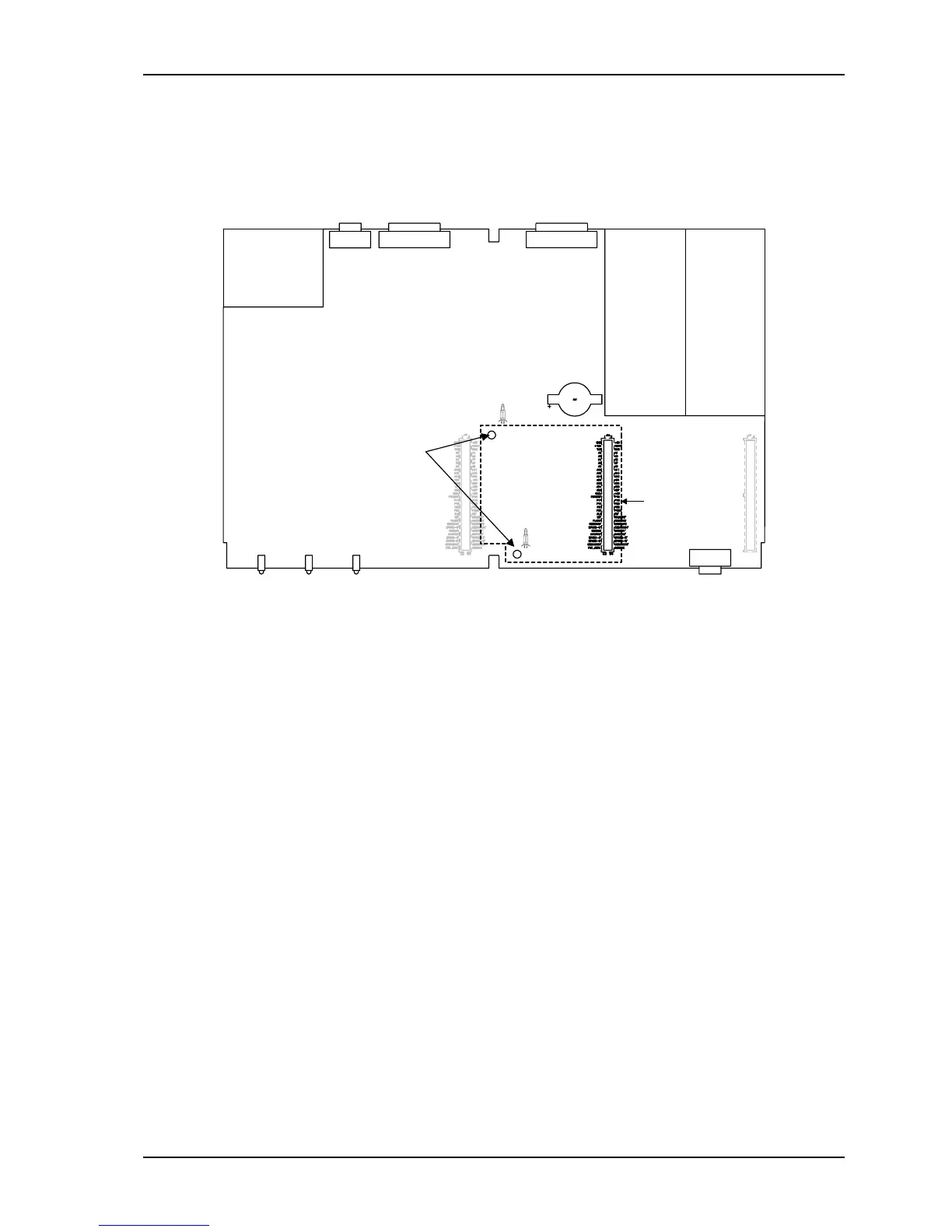
6. Attach two plastic supports to the Control Unit’s motherboard by pressing the clip end of
each support into the two
3
/
16
-inch (5 mm) holes to the left of the central expansion slot.
Use this
expansion slot
Rear
Front
Holes for
supports
Plastic supports
Battery
Figure 5-4: RAM Expansion Board installation
7. With the board’s 64-pin connector facing down and to the right, align the connector with
the central expansion slot on the Control Unit’s motherboard.
8. Press gently but firmly until the board is fully connected. The rounded end of the
supports on the motherboard snaps into the two holes on the expansion board with light
pressure. Remember to lower the metal handle on the RAM board.
9. Install a new battery before putting the Control Unit’s cover back on (see section 5.1.2).
Plug in the power cord, turn on the unit and allow it to reset.
10. If necessary, upgrade the Control Unit’s firmware to the most recent version available.
See section 5.4 for upgrade instructions. Remember to restore the Control Unit’s setup
with the information printed in step 3.
11. Load the subscriber status data into the Control Unit from the backup copy (see upload
command procedure in section 6).
12. Reconnect the host computer.