Product Description Control Unit IV Reference Manual
1-8 529-0004 Ver.3
1.4 Physical characteristics
1.4.1 Enclosure
The Control Unit’s enclosure measures one rack unit high (1.75 in.), and mounts easily in a
standard 19-inch equipment rack. For rackmounting instructions, see Chapter 2. All
connectors are external to the Control Unit. The unit does not need to be opened for normal
operation, except to change the battery.
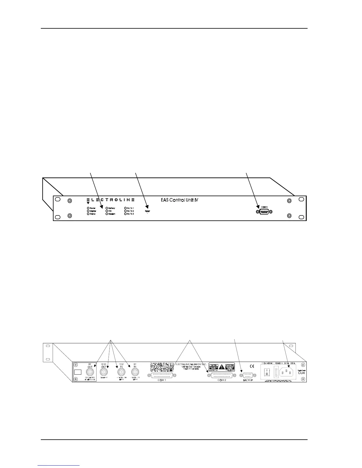
Front panel
All of the Control Unit’s system monitoring LEDs are located on the front panel. In addition
to the LEDs, COM3, which is the setup and diagnostic port, is also readily accessible on the
front panel. For more information on using the COM 3 port, see Chapter 3. For help
interpreting the LEDs, see Chapter 6.
LEDs Reset button Setup port
Figure 1-3: Front panel of the Control Unit IV
Rear panel
All cabling connections, except for the setup connection, are located on the rear panel: RF
inputs and outputs, COM ports, proprietary backup system port, and power entry module.
The Control Unit’s power entry module accepts 120 VAC/60 Hz or 240 VAC/50 Hz power
without requiring any hardware modifications. The appropriate power cord comes with the
Control Unit according to the country in which the unit is used. The Control Unit also comes
with two 250 V/2.5 A fast blow fuses, one of which is a spare fuse, to protect the power
supply from power surges. See Chapter 5 to replace a blown fuse.
RF inputs and outputs COM ports Backup port Power input
Figure 1-4: Rear panel of the Control Unit IV