G
G
4
4
5
5
0
0
0
0
&
&
G
G
3
3
5
5
0
0
0
0
P
P
o
o
r
r
t
t
a
a
b
b
l
l
e
e
P
P
o
o
w
w
e
e
r
r
Q
Q
u
u
a
a
l
l
i
i
t
t
y
y
A
A
n
n
a
a
l
l
y
y
z
z
e
e
r
r
U
U
S
S
E
E
R
R
&
&
I
I
N
N
S
S
T
T
A
A
L
L
L
L
A
A
T
T
I
I
O
O
N
N
G
G
U
U
I
I
D
D
E
E
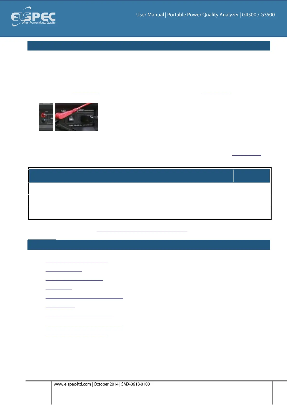
plug in the G4500'S VDC probes:
The G4500 facilitates Auxiliary DC(+) & DC(-) voltage & current inputs & provides an independent
input to the main AC/DC channel DC voltage readings. The measurement range ranges from -
1000VDC to +1000VDC at a rate of once every second. This is mainly suitable for a voltage converter
DC link side reading while the main voltage channels are on the grid side.
Plug in the DC Probes into the applicable sockets located on the Rear Panel - Red(+) &
Black(-):
Connect the measurement end to the measured power source
No configuration is necessary for the automatically recognized DC V/I Probes, you may
however choose to Enable / Disable the recording at your own choosing. See Capture DC.
Galvanic Insulation from Main AC / DC Channels
Go to the next step - Establishing a 1st Time Connection
see also:
About Quick Installation
Unit Powering
About Portable Wiring
Grounding
Establish 1st Time Connection
Unit Access
About Quick Configuration
Verify Measurement Readings
Enable PQZIP Recording