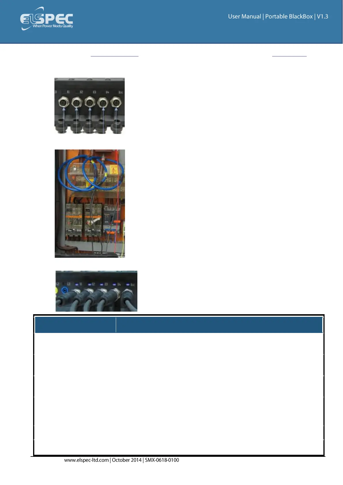
Plug in the Current Probes into the applicable sockets located on the Rear Panel (Pay
attention to the phase connections, as the channels are calibrated according to the clamps -
I1 for I1; I2 for I2; I3 for I3; I4 for I4 & IDC for the DC Clamp):
Connect the measurement end to the measured power source:
The LED light will illuminate confirming a solid connection:
4 (3 Phases & Neutral) +
DC/Ground
I1 to I4: 10 V
Pk
I5: 3 V
Pk
From Clamp
I1 to I4: 10 V
Pk
From Clamp
Clamp On Current Transformer
With mV Output
Clamp On Current Transformer
With mV Output
I1 to I4: 0 to 10 V
Pk
I5: 0 to 3 V
Pk
From Clamp
I1 to I4: 0 to 10 V
Pk
From Clamp
0.05VA (Typical) @ 5 IRMS
0.05VA (Typical) @ 5 IRMS