E-TRA3000 F-S-D-V-C_E-Manual 37/162
3 Mechanical structure
3.1 General
The TRA3000 F-S-D-V-C is ideal for running tests in development/test laboratory environments and for
outdoor service on larger systems. For outdoor service, the TRA3000 F-S-D-V-C can be fitted into a military
case.
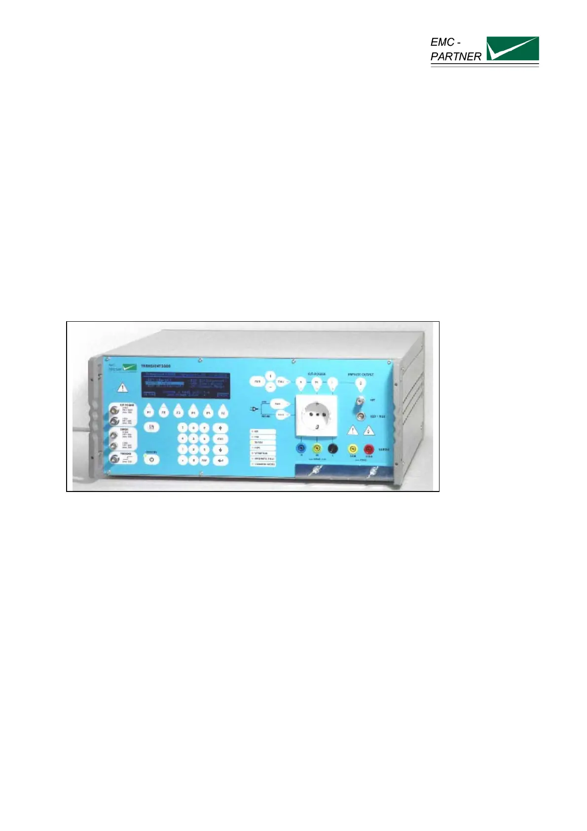
For better understanding, the TRA3000 F-S-D-V-C will be divided into two parts:
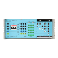
• The left hand part of the TRA3000 F-S-D-V-C contain the control and measurements. The left hand side
of the front panel, is called the control panel.
• The right hand part contains all high voltage circuits, such us high voltage source, high voltage switches,
the impulse-forming network and the coupling / de-coupling network. This part is called the operation
panel.
Fig.3.1
The power connections of the TRA3000 F-S-D-V-C and the EUT are located on the rear panel. With the
EUT power inputs on the rear side and the outputs on the front side an optimum de-coupling is guaranteed.
This arrangement allows test set-up without parallel-running cables.
The TRA3000 F-S-D-V-C is available with different options:
Standard with handles on both side as showed in Figure 3.1. This version is recommended for use in
development and EMC test laboratories.
19“ insert version. The handles are removed and angle brackets are fixed on both sides for fitting the
TRA3000 F-S-D-V-C in a 19“ rack. When the TRA3000 is equipped with an EFT circuit the EFT output
must be maximum 50 cm above the reference ground plane.
Standard with handle in a military case
. This version is recommended for outdoor EMC testing.