TRANSIENT3000
39/162
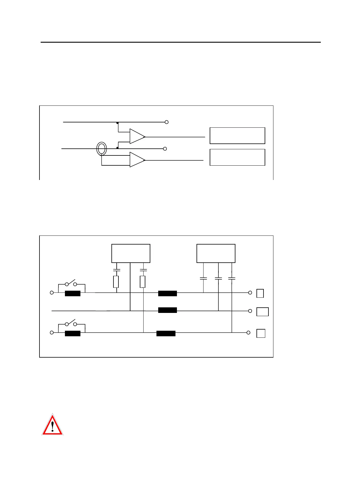
3.3 Measuring Circuit
The SURGE impulse voltage is measured differentially with two internally-located voltage dividers. The
current is measured with a current monitor with differential amplifier. The peak values of voltage and
current are memorised and shown in the display. With the two CRO outputs, the voltage and current
waveform can be monitored on a oscilloscope.
fig. 3.2
3.4 Coupling / De-coupling Network CDN
The coupling / de-coupling network (CDN) of the TRA3000 F-S-D-V-C allows the superimposition of the
EFT or SURGE impulses onto the power line of the EUT. Switching of the different coupling paths can be
programmed. For the voltage DIPS test, the de-coupling network is automatically by-passed.
fig. 3.3
3.5 EUT power supply at DIPS
In the operation mode (DIPS voltage interruption), the switch S1 turns on the EUT Power 1 power source
( undisturbed level). S2 turns on the power to EUT Power 2 (disturbed level). The internal variac can be
replaced by an external variac or PS3 power supply and therefore the EUT Power 2 can be generated by
internal or external means.
For DIP testing, the NEUTRAL must be close to earth potential (PE). If voltage is present on the
Neutral an error will be shown on the TRA3000 F-S-D-V-C display. If the Neutral is not close to
earth potential, an isolation transformer must be used between the mains supply and TRA3000
F-S-D-V-C input..
SURGE high
SURGE low
10 V corresponds
to. 4000 V
10 V corresponds
to. 2000 A
L
PE
N
SURGE EFT
33 nF
9 µ or 18µ
0 Ω or 10 Ω
bypass
bypass