TRANSIENT3000
40/162
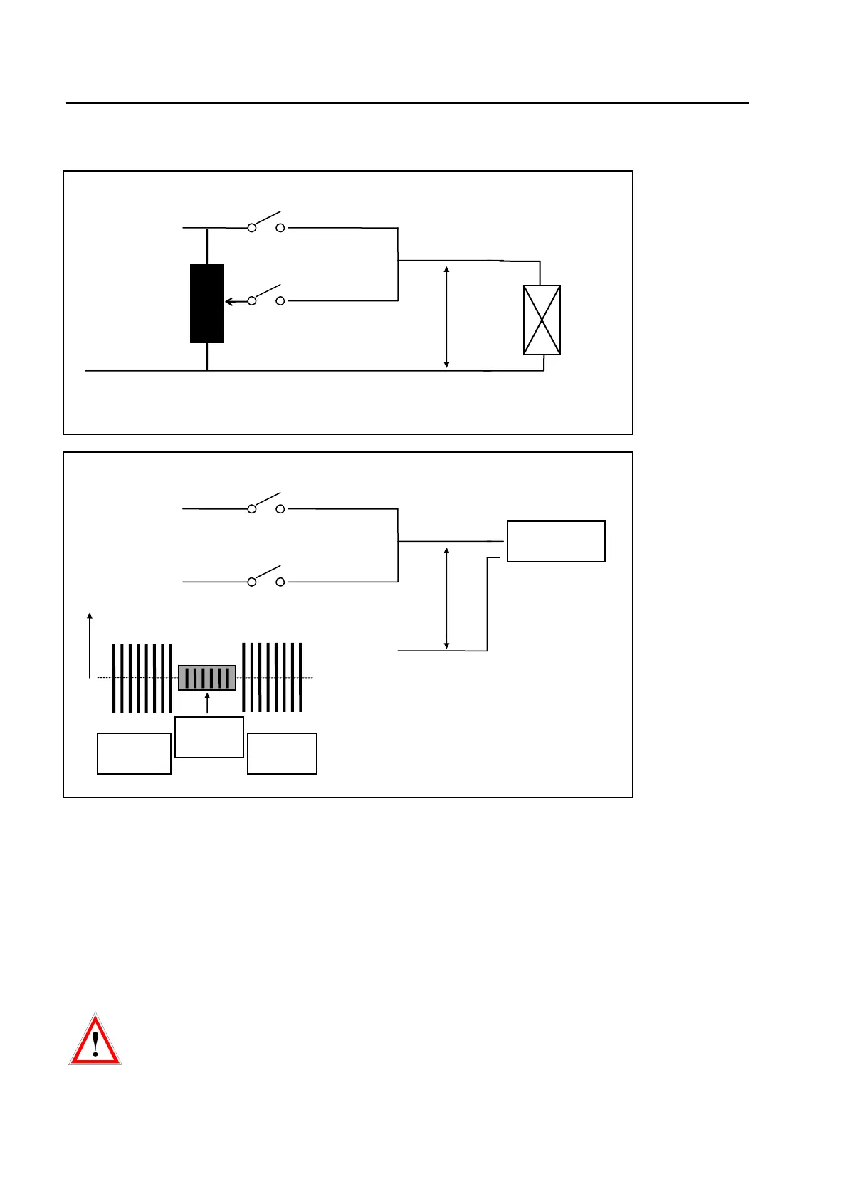
fig. 3.4
Fig. 3.4
At DIPS to 0 % of the power line voltage, two operating conditions can be differentiated:
A) Switch S1 is opened, the voltage of the power decreases at the EUT with the discharge constant of the
EUT (High Z at 0% = ON)
B) Some µs after switch S1 has opened, switch S2 will be closed and the EUT will be discharged via the
circuit EUT Power 2 (High Z at 0% = OFF).
AT High - Z Mode = OFF and large capacitive loads, the large capacitance will be discharged via the
internal variac at the beginning of the interruption. A large current will result, if an interruption to 0% of the
power line voltage is generated. To avoid reducing the life span of the carbon contact electrode of the
variac, it is recommended to make a short circuit with an external bridge between L2 and N of EUT Power
2.
Vrms between EUT Power 1 and EUT Power 2 must be lower than 250V. Use for EUT Power 1
and 2 equal phase L.
The maximum voltage on the inputs of EUT power 1 or EUT power 2 must be lower than 280V.
High voltage s will destroy the varistors on the inputs.
Phase
EUT Power 1
EUT Power 2
EUT Power
Output
S2
S2
U-power
U-power
S1= ON
S2 = OFF
S1= OFF
S2= ON
S1= ON
S2= OFF
U - Power line
L
L
N
N
EUT
External or internal Variac (or
PS3)
Neutral
EUT Power 1
EUT Power 2