TRANSIENT3000
56/162
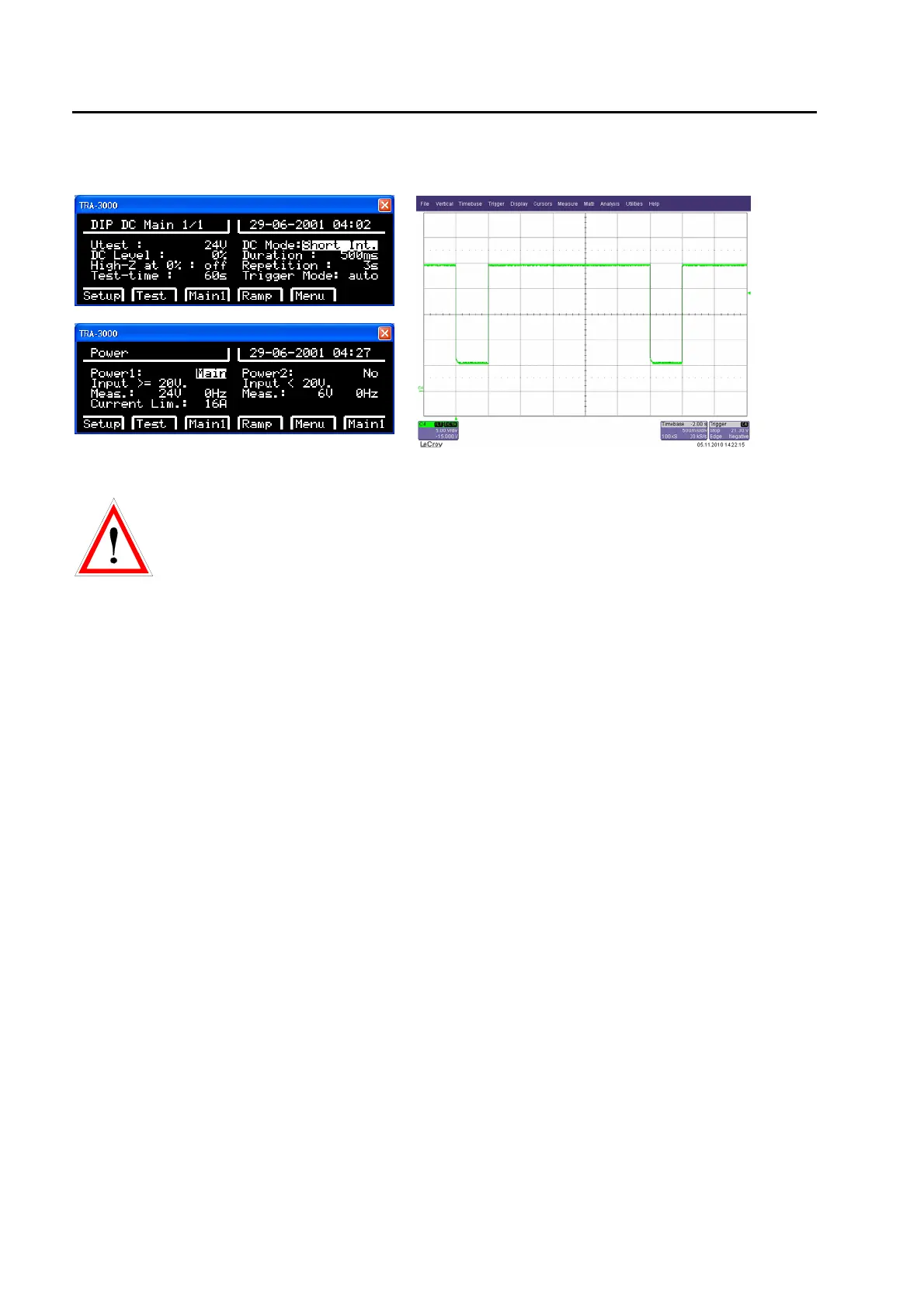
5.4.4 Example
(PWR1: 24Vdc PWR2: 6Vdc)
(voltge PWR1 and PWR2 must be selected on
external power supplys)
Remarks:
• The green LED „Synchro on EUT Power“ has no indication.
• The voltage and current measurement EUT Power is inactive. The measurement circuit is designed for
ac only.
SURGE superimposing on dc
For this kind of test the dc voltage must be connected to input d.c EUT-Power 1. The coupling path L to N
must be selected. The coupling impedance is 10 Ω and 9 µF.
This is an advice from EMCP based on experience of customers, where protection devices have been
destroyed when SURGE tests have been carried out with coupling impedance 18 µF and 2 Ohm between L
and N. In the real installation environment they never had a damage of the equal protection devices. In the
IEC 61000-4-5 no specific chapter deals with different d.c. sources. The only hints for Surge tests on d.c.
supply can be found in the single phase test set up examples.