TRANSIENT3000
44/162
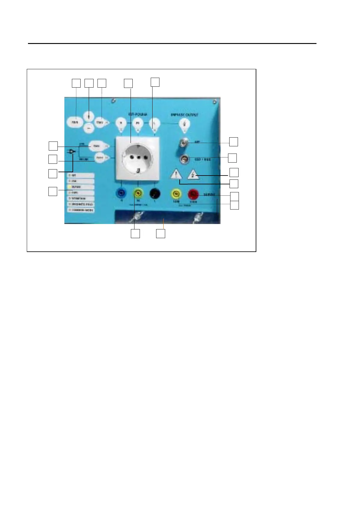
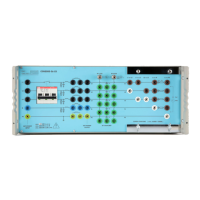
4.1.2 Operation panel
Fig. 4.1.2
4.1.2.1 Button Run (19)
With the „Run“ button, a test can be started or interrupted.
4.1.2.2 Manual Trigger (21)
When manual trigger is programmed and the tester is ready for manual trigger, this will be indicated by the
LED. As soon as the signal occurs the pulse can be released by pressing the manual trigger button.
4.1.2.3 Signalling the EMC test type(26)
The LED (26) signals which of the seven possible EMC test is chosen: ESD, EFT, SURGE, DIPS,
Variation, Magnetic field, Common Mode. A continuous signal indicates which test has been selected in
set-up, while a blinking signal indicates that the test is running.
4.1.2.4 Indication of the coupling path (22)
The four LEDs indicate which path is receiving the disturbance . The three lines of the EUT power, or the
direct high voltage outputs. The signals appear as soon as a test is active. With the buttons above the LED
indicators, coupling path can be changed also during operation.
4.1.2.5 Single phase power output power plug Schuko(23) or banana plug (33) type.
When superposing the disturbance onto the EUT power line, the power cord of the EUT must be connected
with the Socket (23). EMC PARTNER offers adapters for the different types of power cord connectors for
different countries.
19 20 21
22
23
24
36
25
26
27
29
30
31
33 34
35
32