EasyManuals Logo

Emerson DSM314 User Manual

Emerson DSM314
519 pages
To Next Page IconTo Next Page
To Previous Page IconTo Previous Page
Page #32 background imageLoading...
Page #32 background image
User Manual Chapter 2
GFK-1742F Jan 2020
System Overview 21
2.
Check SVU Amplifier Channel Switch Settings
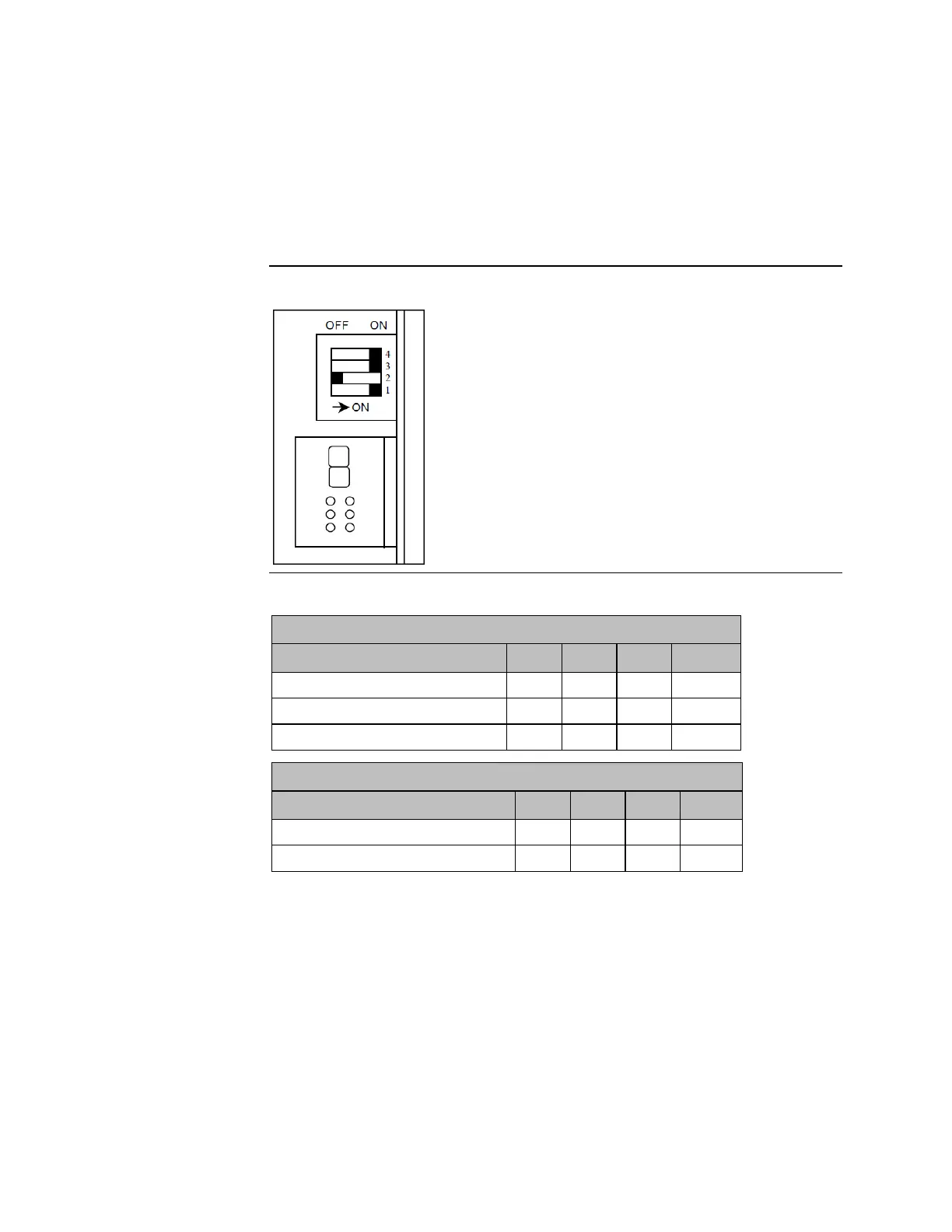
Confirm that the Channel Switches (DIP switches), located behind the SVU amplifier
door, are set as shown in the following tables. Note that the OFF position is to the left,
and the ON position is to the right. Note also, that the switches are numbered from
bottom to top (Switch 1 is the bottom switch). For example, in Figure 7, Switches 1, 3,
and 4 are shown ON, and switch 2 is shown OFF.
Figure 7: SVU Amplifier Channel Switches
Table 6: SVU Amplifier Channel Switch Settings
Amplifier SVU1-80
Regenerative Discharge Unit
SW1
SW2
SW3
SW4
Built-in (100 W)
ON
OFF
ON
ON
Separate ZA06B-6089-H500 (200 W)
ON
OFF
ON
OFF
Separate ZA06B-6089-H713 (800 W)
ON
OFF
OFF
OFF
Amplifier SVU1-130
Regenerative Discharge Unit
SW1
SW2
SW3
SW4
Built-in (400 W)
ON
OFF
ON
ON
Separate ZA06B-6089-H711 (800 W)
ON
OFF
ON
OFF
(To connect additional amplifiers, repeat steps B, C and D above for each additional
amplifier.)

Table of Contents

Questions and Answers:

Question and Answer IconNeed help?

Do you have a question about the Emerson DSM314 and is the answer not in the manual?

Emerson DSM314 Specifications

General IconGeneral
BrandEmerson
ModelDSM314
CategoryController
LanguageEnglish

Related product manuals