User Manual Chapter 2
GFK-1742F Jan 2020
System Overview 27
6.
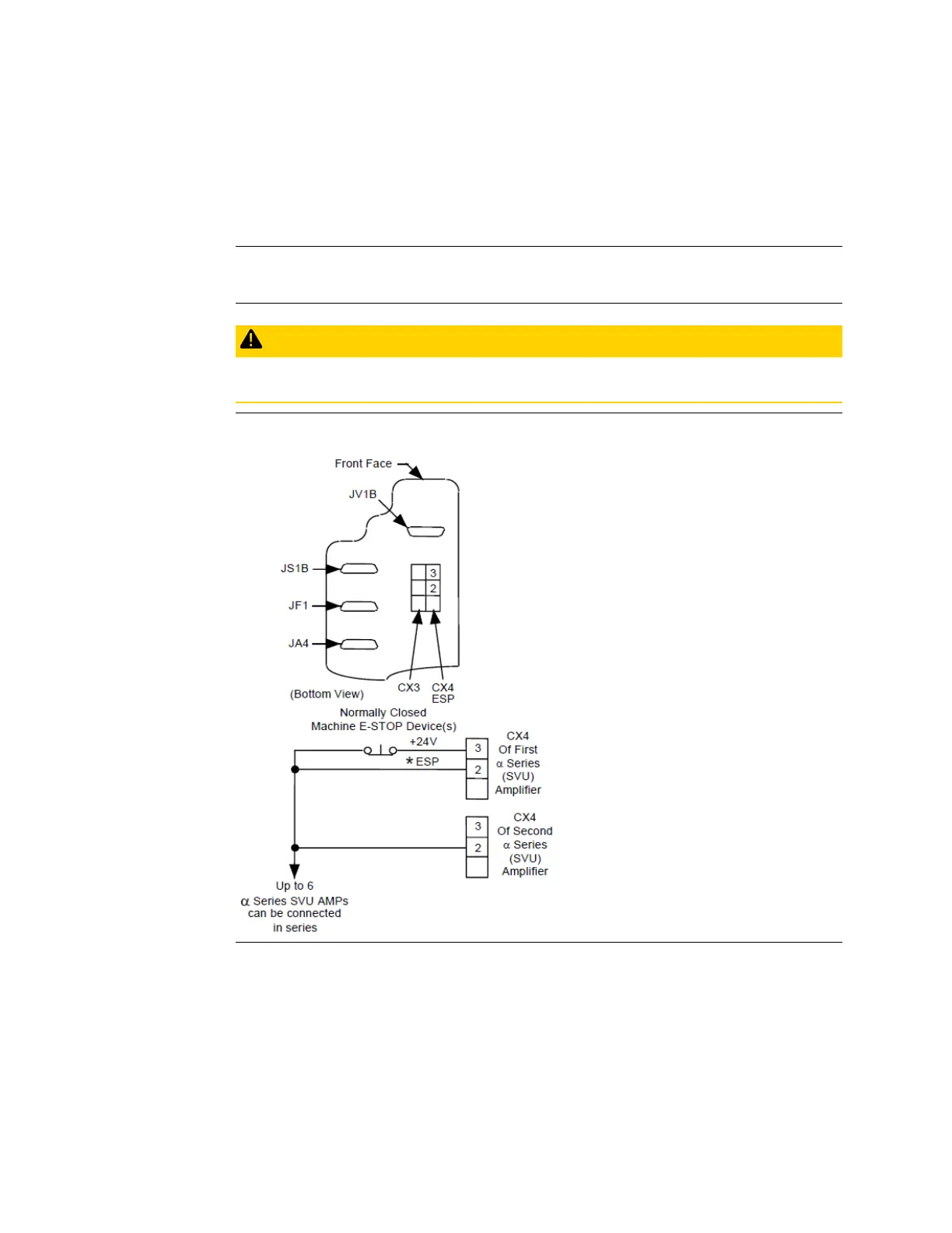
Connect the Machine Emergency Stop to the
α
Series Digital Servo Amplifier
Pin 3 of connector CX4, located on the bottom of the
α
Series (SVU) amplifier, supplies +24
volts DC for the E-STOP circuit. Route this through the machine E-STOP circuit so that there
is +24 volts DC to pin 2 when not in E-STOP. If no E-STOP switch is used this connection must
be made with a wire jumper.
Note: You must supply the cable for this connection. Keyed connector plugs marked as connector X and
terminal connector pins are included with the amplifier package. You must install this connection
as a switch or jumper for the amplifier to operate.
CAUTION
Do not apply any external voltage to this connector.
Figure 12: Connecting Emergency Stop to the
Series Servo Amplifier
For more information, refer to the
Series Servo Amplifier (SVU) Descriptions Manual, GFZ-
65192EN.