Piping Schematics
120
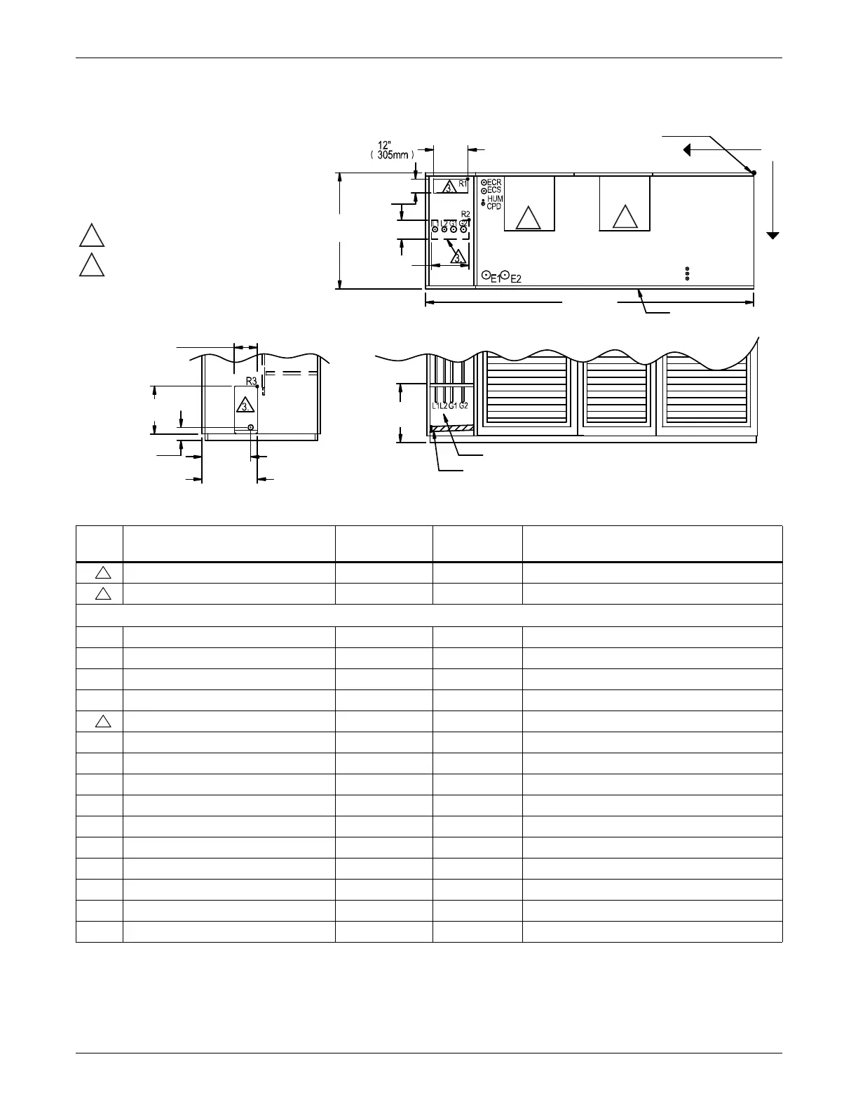
Figure 93 Primary connection locations—upflow, air-cooled, 53-77kW (15-22 ton), scroll compressor
models
Point Description
X
inches (mm)
Y
inches (mm)
Connection Size / Opening
inches (mm)
R1 Refrigerant Access (Top) 83-5/8 (2124) 2 (51) 12 x 4 (305 x 102)
R2 Refrigerant Access (Bottom) 82-3/4 (2102) 14-3/4 (374) 12-3/16 x 4 (310 x 102)
53kW (15 tons)/70 & 77kW (20 & 22 ton)
L1 Liquid Line System 1 94-11/16 (2405) 16-3/4 (425) 1/2 / 5/8 Cu Sweat
L2 Liquid Line System 2 91-7/8 (2334) 16-3/4 (425) 1/2 / 5/8 Cu Sweat
G1 Hot Gas Discharge 1 88-3/4 (2254) 16-3/8 (416) 7/8 / 1-1/8 Cu Sweat
G2 Hot Gas Discharge 2 85-9/16 (2173) 16-3/8 (416) 7/8 / 1-1/8 Cu Sweat
R3 Refrigerant Access (Side) - - 6 x 17-3/16 (152 x 437)
CGD* Condensate Gravity Drain - - 3/4 FPT
CPD Condensate Pump Discharge (Opt) 79-5/16 (2015) 11-7/8 (302) 1/2 Cu Sweat
HUM Humidifier Supply Line 79-5/16 (2015) 9-7/8 (251) 1/4 Cu Sweat
ECS** Econ-O-Coil Supply 78-5/8 (1998) 7-7/8 (200) 2-1/8 Cu Sweat
ECR** Econ-O-Coil Return 78-5/8 (1998) 4-5/8 (117) 2-1/8 Cu Sweat
E1 Electrical Connection (High Voltage) 75-3/8 (1915) 30 (762) 2-1/2
E2 Electrical Connection (High Voltage) 69-7/8 (1775) 30 (762) 2-1/2
LV1 Electrical Connection (Low Voltage) 19-1/2 (495) 29-1/16 (738) 7/8
LV2 Electrical Connection (Low Voltage) 19-1/2 (495) 30-1/2 (775) 7/8
LV3 Electrical Connection (Low Voltage) 19-1/2 (495) 31-15/16 (811) 7/8
* Field-pitch condensate drain line a minimum of 1/8" (3.2 mm) per foot (305 mm). All units contain a factory-installed condensate trap. Do not
trap external to the unit. Drain line may contain boiling water. Select appropriate drain system materials. The drain line must comply with all
local codes.
** Supplied on Dual-Cool systems only (four-pipe system)
Factory Location
Front
CGD*
CGD*
Top View
Left Side Section View
Front Section View
(Left Front Panel Not Shown)
NOTE
1. Drawing not to scale.
2. Tolerance on all piping dimensions
is ±1/2" (13mm).
3. Field-routed alternatives for refrigerant
gas and liquid line connection points.
4. See submittal page DPN001191 for
blower outlet and deck dimensional data.
4" (102mm)
4"
(102mm)
6"
(152mm)
3-7/8"
(98mm)
17-3/16"
(437mm)
Blower
Outlet
Blower
Outlet
DPN001213
Rev. 1
35"
(889mm)
17-1/16"
(433mm)
98"
(2489mm)
Lv1
LV2
LV3
X
Y
O
14-1/4"
(362mm)
15-7/8"
(403mm)
12-13/16"
(325mm)
All dimensions from
rear corner of unit
including panels
4
4
 Loading...