Piping Schematics
108
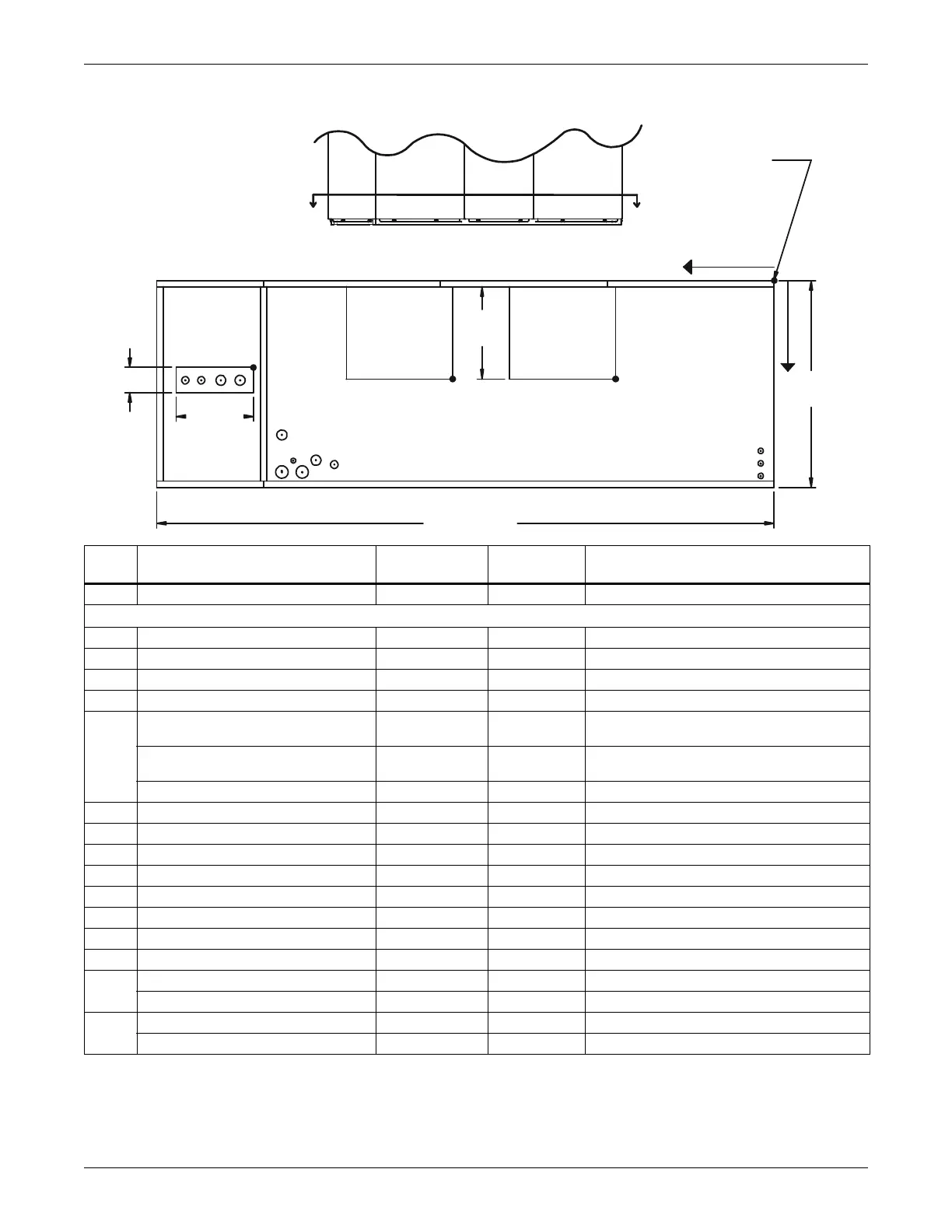
Figure 81 Primary connection locations—downflow, air-Cooled, 53-77kW (15-22 ton) with scroll
compressor models
Point Description
X
in. (mm)
Y
in. (mm)
Connection Size / Opening
in. (mm)
R Refrigerant Access 81-3/4 (2076) 14-3/4 (374) 12-3/16 x 4 (310 x 102)
53kW (15 tons) / 70&77kW (20&22 tons)
L1 Liquid Line System 1 94-11/16 (2405) 16-3/4 (425) 1/2" / 5/8" Cu Sweat
L2 Liquid Line System 2 91-7/8 (2334) 16-3/4 (425) 1/2" / 5/8" Cu Sweat
G1 Hot Gas Discharge 1 88-3/4 (2254) 16-3/8 (416) 7/8" / 1-1/8" Cu Sweat
G2 Hot Gas Discharge 2 85-9/16 (2173) 16-3/8 (416) 7/8" / 1-1/8" Cu Sweat
CD
Condensate Drain
(infrared humidifier or no humidifier)*
69-1/4 (1759) 30 (762) 3/4" FPT
Condensate Drain
(steam generating humidifier)*
69-1/4 (1759) 30 (762) 1-1/4" FPT
W/ Optional Pump 69-1/4 (1759) 30 (762) 1/2" Cu Sweat
HUM Humidifier Supply Line 76-1/2 (1943) 29 (736) 1/4" Cu Sweat
ECS** Econ-O-Coil Supply 78-5/8 (1997) 22-1/4 (565) 2-1/8" Cu Sweat
ECR** Econ-O-Coil Return 72 (1829) 29 (737) 2-1/8" Cu Sweat
E1 Electrical Conn. (High Volt) 78-1/2 (1994) 31-1/8 (790) 2-1/2"
E2 Electrical Conn. (High Volt) 75-3/8 (1915) 31-1/8 (790) 2-1/2"
LV1 Electrical Conn. (Low Volt) 1-7/8 (48) 28-1/2 (724) 7/8"
LV2 Electrical Conn. (Low Volt) 1-7/8 (48) 30-1/4 (768) 7/8"
LV3 Electrical Conn. (Low Volt) 1-7/8 (48) 32 (813) 7/8"
B1
Blower Outlet (15 x 15) 23-1/8 (587) 18-1/16 (459) 18-3/4 x 16-1/16 (476 x 408)
Blower Outlet (15 x 11) 27-3/4 (705) 18-1/16 (459) 14-3/4 x 16-1/16 (375 x 408)
B2
Blower Outlet (15 x 15) 50-3/8 (1280) 18-1/16 (459) 18-3/4 x 16-1/16 (476 x 408)
Blower Outlet (15 x 11) 54-3/8 (1381) 18-1/16 (459) 14-3/4 x 16-1/16 (375 x 408)
* Field pitch condensate drain line a minimum of 1/8" (3.2 mm) per foot (305 mm). All units contain a factory-installed condensate trap. Do
not trap external to the unit. Drain line may contain boiling water. Select appropriate drain system materials. The drain line must comply
with all local codes.
** Supplied on Dual Cooling Systems only (4 pipe system)
L1
L2
G1
G2
R
O
X
Y
A
A
4" (102mm)
NOTE: Drawing not to scale.
Tolerance on all piping
dimensions is ± 1/2" (13mm).
FRONT OF UNIT
FRONT VIEW
SECTION A-A
All dimensions from
rear corner of unit
including panels
ECS
ECR
CD
E1 E2
HUM
LV1
LV2
LV3
98" (2489mm)
12-3/16"
(310mm)
35"
(889mm)
DPN00929
Rev. 4
B1
BLOWER
OUTLET
BLOWER
OUTLET
B2
16-1/16"
(408mm)
 Loading...