Check and clear obstructions in tubing during routine maintenance.
Risk of electric shock. Can cause injury or death.
mode. Some internal components require and receive power even during the “unit off” mode of
the Liebert iCOM control.
J18
J19
J17
J20
J16
J21
J15
J22
J14
J13
J12
J1 1
P1 1
1
1
P12
J1
J2
J3
J4
J5
J6
J7
Current
Transformer
J23
J10
J8
J9
J25
J26
J24
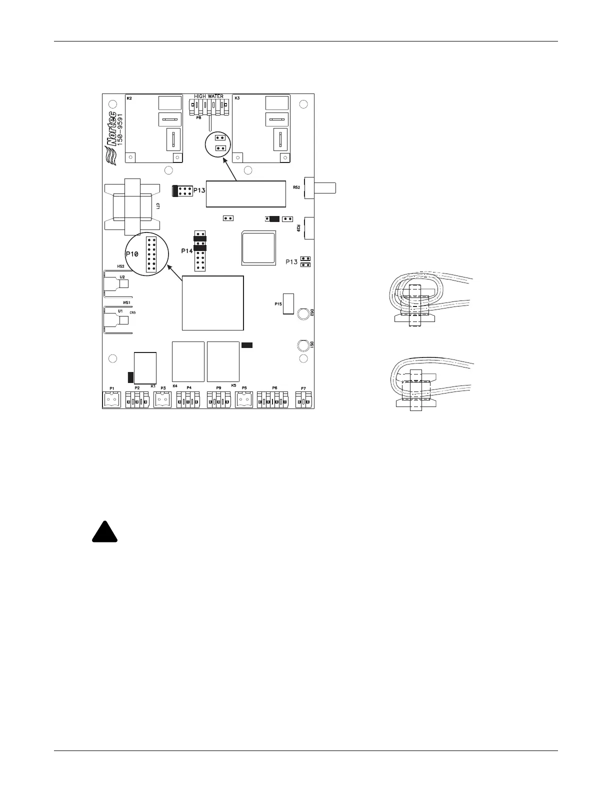
200V/208V: J6, J9, J15*, J17*, J19*, J10*, J23*, P11 pin (2-3)*
230V: J5, J9, J15*, J17*, J19*, J10*, J23*, P11 pin (2-3)*
380V/415V: J3, J8, J15*, J17*, J19*, J10*, J23*, P11 pin (2-3)*
460V: J2, J8, J15*, J17*, J19*, J10*, J23*, P11 pin (2-3)*
575V: J1, J8, J15*, J17*, J19*, J10*, J23*, P11 pin (2-3)*
To configure the PCB to the proper voltage,
the jumpers should be set as follows:
PCB is configured for: MES-L
(* = Factory setting; do not adjust)
Capacity adjust
(Default at 100%)
Sealed,
do not adjust
Green
LED
Yellow
LED
CURRENT TRANSFORMER
For MES-L 10, loop current-sensing wire twice
through current-sensing coil.
For MES-L 20, loop current-sensing wire once
through current-sensing coil.
J6: 200-208
J5: 230V
J3: 380-415
J2: 460V
J1: 575V
Mains Voltage
Select Jumpers
HW Sensor Jumpers
J9: Low Voltage 200-240V
J8: High Voltage 380-600V
 Loading...