Piping Schematics
113
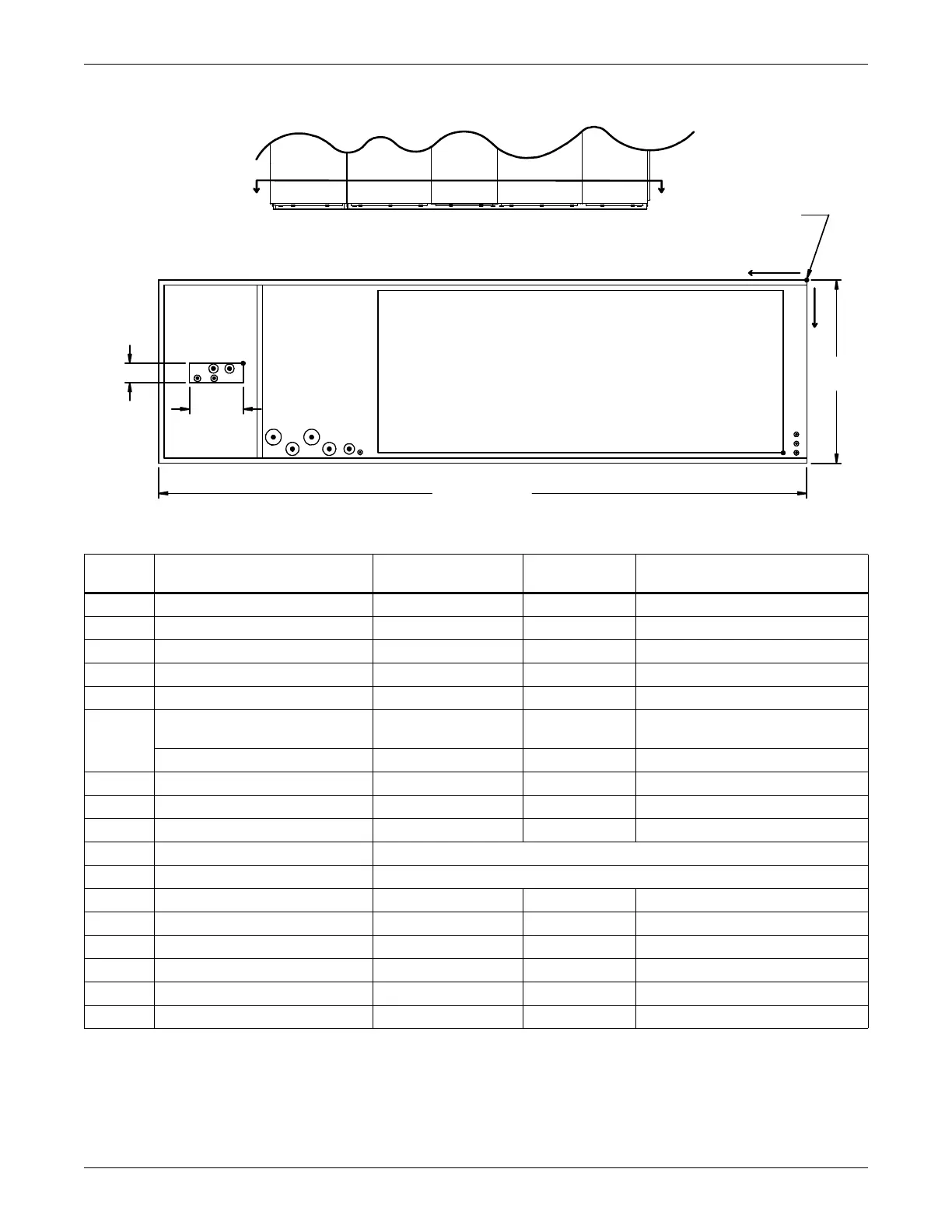
Figure 86 Primary connection locations—downflow, air-cooled, 105kW (30 ton), all compressor models,
with EC fan
Point Description
X
in. (mm)
Y
in. (mm)
Connection Size / Opening
in. (mm)
R Refrigerant Access 109 (2769) 15-3/4 (400) 16-7/16 (418) x 4 (102)
L1 Liquid Line System 1 121-3/4 (3092) 16-3/4 (425) 5/8 Cu Sweat
L2 Liquid Line System 2 118-1/8 (3000) 16-3/4 (425) 5/8 Cu Sweat
G1 Hot Gas Discharge 1 118-1/4 (3004) 14-1/4 (362) 1-1/8 Cu Sweat
G2 Hot Gas Discharge 2 115-5/8 (2937) 14-1/4 (362) 1-1/8 Cu Sweat
CD
Condensate Drain (Infrared
Humidifier Or No Humidifier)*
87-3/8 (2220) 31 (787) 3/4 FPT
W/ Optional Pump 83-13/16 (2129) 30 (762) 1/2 Cu Sweat
HUM Humidifier Supply Line 85-5/16 (2167) 32-1/2 (825) 1/4 Cu Sweat
ECS ** Econ-O-Coil Supply 101-7/8 (2588) 29 (737) 2-5/8 Cu Sweat
ECR ** Econ-O-Coil Return 94-9/16 (2402) 29 (737) 2-5/8 Cu Sweat
HS Hot Water Reheat Supply CONSULT FACTORY
HR Hot Water Reheat Return CONSULT FACTORY
E1 Electrical Conn. (High Volt) 98-1/8 (2492) 31 (788) 2-1/2
E2 Electrical Conn. (High Volt) 91 (2311) 31 (788) 2-1/2
LV1 Electrical Conn. (Low Volt) 2 (51) 29 (737) 7/8
LV2 Electrical Conn. (Low Volt) 2 (51) 30-7/8 (784) 7/8
LV3 Electrical Conn. (Low Volt) 2 (51) 32 (813) 7/8
B1 Blower Outlet 4-1/2 (114) 33 (838) 77-3/8 x 30 (1965 x 762)
* Field pitch condensate drain line a minimum of 1/8" (3.2 mm) per foot (305 mm). All units contain a factory-installed condensate trap. Do
not trap external to the unit. Drain line may contain boiling water. Select appropriate drain system materials. The drain line must comply
with all local codes.
** Supplied on Dual Cooling Systems only (four-pipe system)
R
L1 L2
G1G2
DPN002154
Rev. 0
FRONT OF UNIT
FRONT VIEW
SECTION A-A
Note: Drawing not to scale.
Tolerance on all piping
dimensions is ± 1/2" (13mm).
ECS
ECR
CD
E1
E2
LV1
LV2
LV3
Y
A
A
All dimensions from
rear corner of unit
including panels
BLOWER
OUTLET
35"
(889mm)
B1
132" (3353mm)
4" (102mm)
16-7/16"
(418mm)
HUM
X
O
 Loading...