Piping Schematics
122
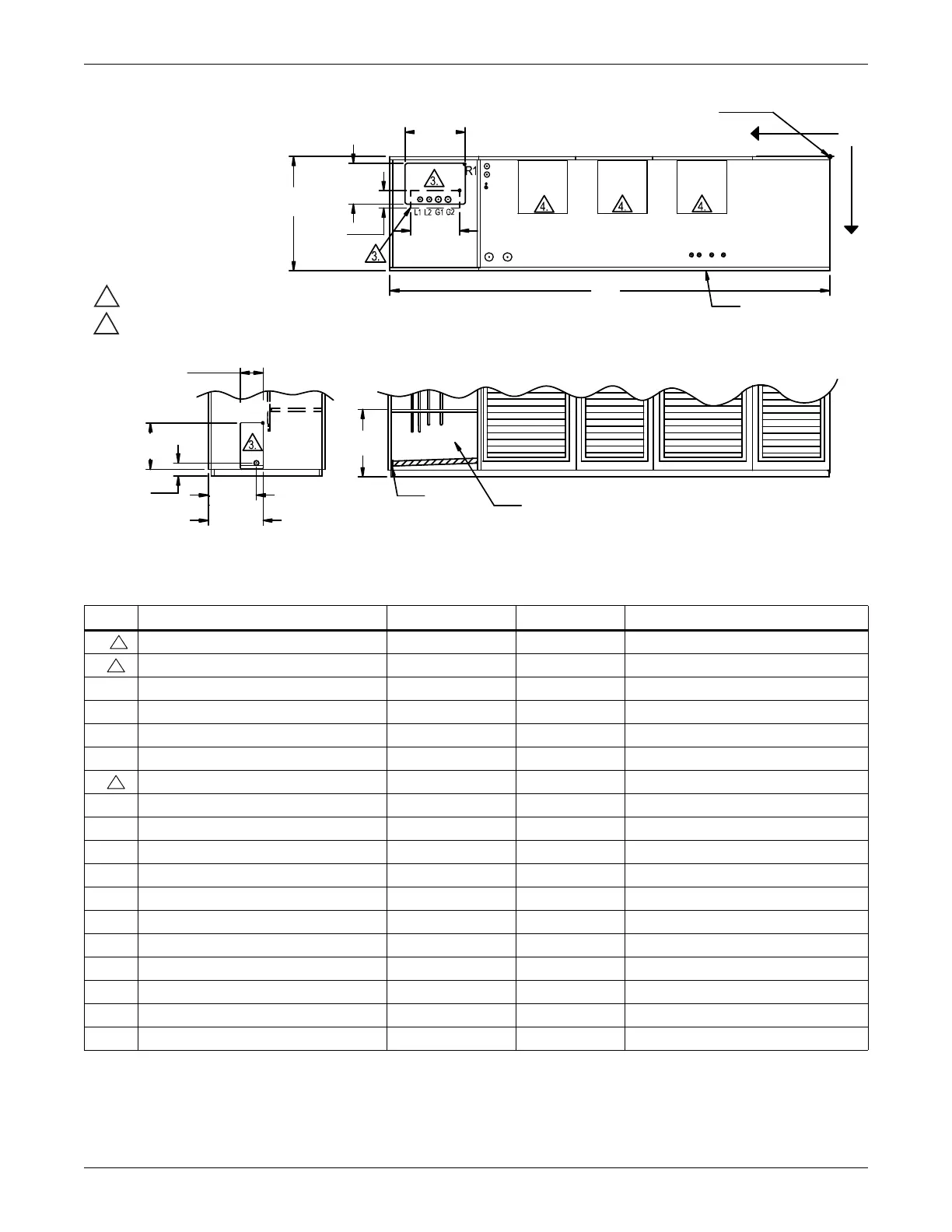
Figure 95 Primary connection locations—upflow, air-cooled, 105kW (30 ton), all
Table 57 Piping data—upflow, air-cooled 105kW (30 ton), all
Point Description
X Y Connection Size / Opening
R1 Refrigerant Access (Top) 106-7/8 (2715) 1-7/8 (48) 22-1/2 x 15-3/16 (572 x 386)
R2 Refrigerant Access (Bottom) 109-1/8 (2772) 13-7/8 (352) 16-7/16 x 4 (418 x 102)
L1 Liquid Line System 1 121-3/4 (3092) 16-3/4 (425) 5/8 Cu Sweat
L2 Liquid Line System 2 118-1/8 (3000) 16-3/4 (425) 5/8 Cu Sweat
G1 Hot Gas Discharge 1 118-1/4 (3004) 14-1/4 (362) 1-1/8 Cu Sweat
G2 Hot Gas Discharge 2 115-5/8 (2937) 14-1/4 (362) 1-1/8 Cu Sweat
R3 Refrigerant Access (Side) - - 6 x 17-3/16 (152 x 437)
CGD* Condensate Gravity Drain - - 3/4 FPT
CPD Condensate Pump Discharge (Opt) 102-3/8 (2600) 13-5/8 (346) 1/2 Cu Sweat
HUM Humidifier Supply Line 101-1/8 (2569) 13-1/8 (333) 1/4 Cu Sweat
ECS Econ-O-Coil Supply 101-1/8 (2569) 10-1/4 (260) 2-5/8 Cu Sweat
ECR Econ-O-Coil Return 101-1/8 (2569) 5-1/4 (133) 2-5/8 Cu Sweat
E1 Electrical Conn. (High Volt) 98-1/2 (2502) 30 (762) 2-1/2
E2 Electrical Conn. (High Volt) 93 (2362) 30 (762) 2-1/2
LV1 Electrical Conn. (Low Volt) 41-1/8 (1045) 30-3/8 (772) 7/8
LV2 Electrical Conn. (Low Volt) 38-7/8 (987) 30-3/8 (772) 7/8
LV3 Electrical Conn. (Low Volt) 35-1/8 (892) 30-3/8 (772) 7/8
LV4 Electrical Conn. (Low Volt) 31-5/8 (803) 30-3/8 (772) 7/8
* Field pitch condensate drain line a minimum of 1/8" (3.2 mm) per foot (305 mm). All units contain a factory-installed condensate trap. Do
not trap external to the unit. Drain line may contain boiling water. Select appropriate drain system materials. The drain line must comply
with all local codes.
TOP VIEW OF UNIT
LV1
LV2
LV3
LV4
E1
E2
X
O
ECS
ECR
HUM
CPD
Blower
Outlet
Blower
Outlet
Blower
Outlet
L1
L2
G1
G2
R2
CGD*
6"
(152mm)
20-1/16"
(509mm)
R3
Factory Location
FRONT SECTION VIEW OF UNIT
(Left Front Panel Not Shown)
LEFT SIDE SECTION VIEW OF UNIT
All dimensions from
rear corner of unit
including panels
Front Of Unit
DPN001257
Rev. 0
Y
3-7/8"
(98mm)
17-3/16"
(437mm)
CGD*
15-7/8"
(403mm)
16-7/16"
(418mm)
22-1/2"
(572mm)
15-3/16"
(386mm)
4"
(102mm)
14-1/4"
(362mm)
35"
(889mm)
132"
(3353mm)
NOTES:
1. Drawing not to scale.
2. Tolerance on all piping dimensions
is ± 1/2" (13mm).
3. Field routed alternatives for refrigerant
gas and liquid line connection points.
4. See submittal page DPN001192 for
blower outlet and deck dimensional data.
 Loading...