Pre-Installation Guidelines
8
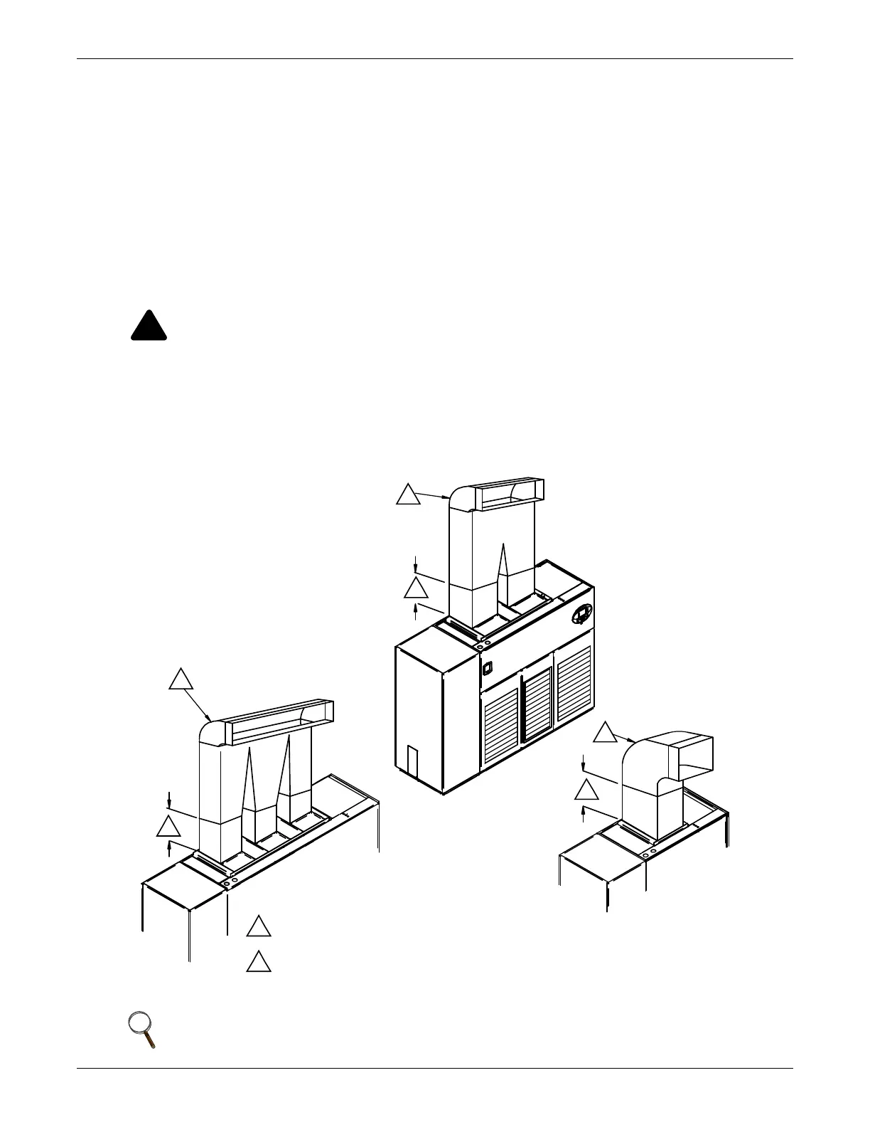
3.3 Air Distribution—Upflow Units
Various configurations are available:
• Front return
• Rear return
•Top-front supply
• Top-rear supply
For in-room applications with supply and return grilles, several feet of clearance must be maintained
at the intake and discharge of the unit.
Upflow rear-return configurations use a filter box attached to the back of the Liebert DS. Allow 25"
(635 mm) on one side of the unit for access to the rear return filter box. Refer to the rear return
installation sheet, 187230P1, inside the rear return filter box package.
Figure 5 Upflow ducting configurations
WARNING
Risk of high-speed moving parts. Can cause injury or death.
Disconnect all local and remote electric power supplies before working in the unit.
Do not operate upflow units without installing a plenum, ductwork or guard over the blower
opening(s) on the top surface of the unit cabinet.
Ductwork must be connected to the blower(s), or a plenum must be installed on the blower
deck for protection from rotating blower wheel(s) on upflow units.
NOTE
Drain traps are qualified to a return duct static of negative 1.5 i.w.g. (-1.5 i.w.g).
DPN001156
Rev. 0
* Follow standard practices on all duct work.
1
1
1
1
2
2
2
2
Straight section of duct off of unit to be 1.5 to 2.5 times
the longest blower dimension.
Typical ducting shown; ducting may run to either side.
 Loading...