Piping Schematics
94
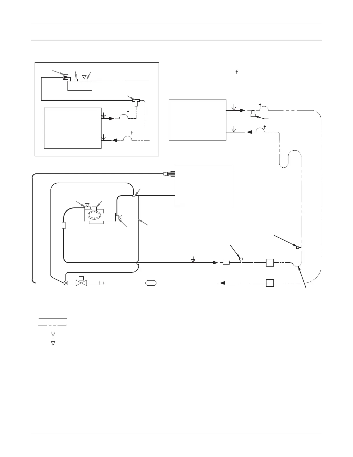
10.0 PIPING SCHEMATICS
Figure 67 Piping schematic—air-cooled, semi-hermetic compressor models
OPTIONAL FIELD INSTALLED
FUSIBLE PLUG
Check Valve
Relief Valve
Service
Valve
LIQUID RETURN
LIEBERT LEE-TEMP RECEIVER
Head Pressure
Control Valve
CONDENSER
COIL
(LIEBERT LEE-TEMP)
HOT GAS DISCHARGE
CONDENSER
COIL
(FAN SPEED or VFD)
LIQUID
EVAPORATOR
COIL
* For rises over 25ft. (7.6m),
trap every 20ft. (6m) or
at evenly spaced points
* Trap at base
of risers longer
than 5ft. (1.5m)
Field installed relief valve(s) required
for 50Hz EU CE units rated maximum
480 PSIG (33 Bar).
Service
Valve
Cylinder
Unloader(s)
SUCTION
External
Equilizer
Sensing
Bulb
Muffler
COMPRESSOR
Service
Valve
**Muffler
HOT GAS DISCHARGE
LIQUID RETURN
*Isolation
Valve
*Isolation
Valve
* Components are not supplied
by Emerson but are recommended for
proper circuit operation and
maintenance
** Components supplied by Emerson
and must be field-installed (70kW,
77kW & 105kW models only)
NOTES: Schematic representation shown. Do not use for specific connection locations.
Two refrigeration circuits provided. Single refrigeration circuit shown for clarity.
SERVICE / SCHRADER (ACCESS) CONNECTION WITH VALVE CORE
DPN000797
REV 5
LIEBERT LEE-TEMP
REFRIGERANT PIPING
Inverted Trap on discharge
& liquid lines to extend above
base of coil by a minimum of
7-1/2" (190mm)
Filter Drier
Sight
Glass
Solenoid
Valve
Expansion
Valve
FIELD PIPING
SERVICE / SCHRADER (ACCESS) CONNECTION, NO VALVE CORE
 Loading...