DSG-423 GENERAL INFORMATION
01-18
Camshaft Lobe Lift
Check the lift of each lobe in consecutive order and
make a note of the readings.
1. Remove the valve covers.
2. Remove the rocker arm seat bolts, rocker arm seat
and rocker arms (if equipped).
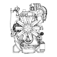
3. Make sure the lash adjuster is seated against
camshaft. Install the dial Indicator with Bracketry so
the ball socket adapter of the indicator is on top of
the hydraulic lash adjuster or the Cup Shaped
Adapter is on top of the push rod and in the same
plane as the lash adjuster push rod movement.
4. On engines with overhead cam, install the dial
Indicator with Bracketry so the plunger is on top of
the camshaft lobe and in the same plane as the
camshaft lobe movement.
5. Remove the spark plugs.
6. Connect an auxiliary starter switch in the starting
circuit. Crank the engine with the ignition switch in
the OFF position. Bump the crankshaft over until the
indicator is measuring on the base circle of the
camshaft lobe (in its lowest position). If checking
during engine assembly, turn the crankshaft using a
socket or ratchet.
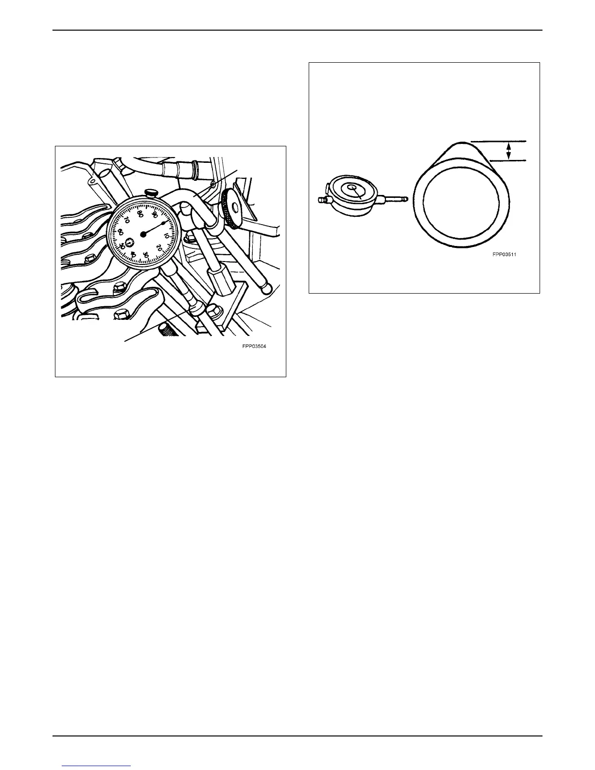
7. Zero the dial indicator. Continue to rotate the
crankshaft slowly until the camshaft lobe is in the
fully-raised position (highest indicator reading).
NOTE: If the lift on any lobe is below specified service
limits, the camshaft and any component operating on
worn lobes must be replaced.
Typical Engine with Push Rods
Cup Shaped
Dial
Indicator
Adapter