L1800 Revision A
Disassembly And Assembly Disassembling the CISS section 106
Confidential
3.7.4.2 Top Cover 3.7.4.3 Tube Valve Holder Front/Rear
Attach the Refilling Ink Label on the position shown in the figure above.
When attaching the Top Cover Label, align it with the markings on the Top Cover as
shown in the figure above.
Marking Marking
Top Cover Label
Top Cover Label
Top Cover
13 ± 1 mm
Top Cover
Refilling Ink Label
Refilling Ink Label
6 ± 1 mm
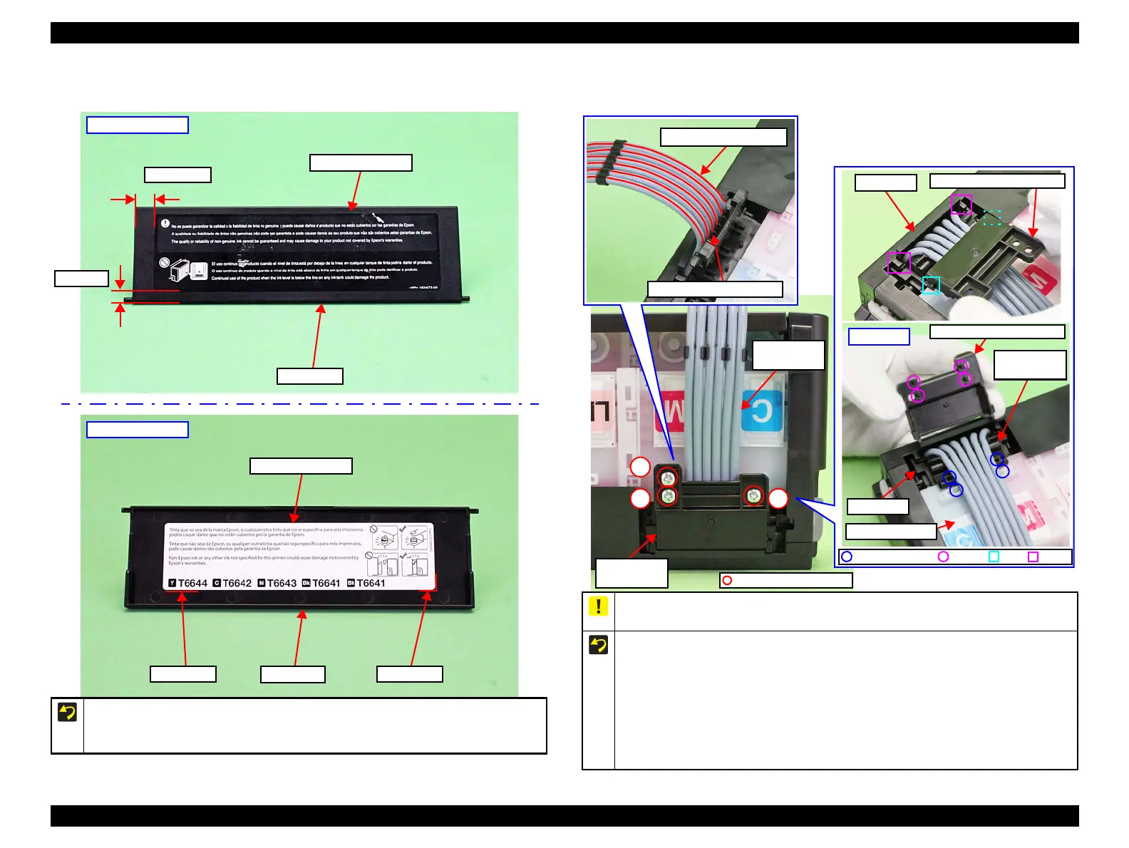
When routing the Ink Supply Tank Tubes, align them with their red lines facing the
Tube Valve Holder Front without any twist.
Follow the procedure below when installing the Tube Valve Holder Rear.
1. Insert the ribs (x2) of the Tube Valve Holder Rear under the hooks (x2) of the Valve
Case.
2. Align the dowels (x4) of the Tube Valve Holder Rear with the positioning holes
(x2) of the Ink Supply Tank and the positioning holes (x2) of the Tube Valve
Holder Front.
3. Make sure no Ink Supply Tank Tubes are caught, then secure it with the screws (x3)
in the order shown in the above figure.
Hook
CBP. 3X6 (4±1 kgf.cm)
Valve Case
Tube Valve Holder Rear
Tube Valve Holder Front
Ink Supply Tank Tube
Back side
Tube Valve Holder Rear
Valve Case
Ink Supply Tank
Tube Valve
Holder Front
Positioning Hole Dowel
Tube Valve
Holder Rear
Ink Supply
Tank Tube

 Loading...