L1800 Revision A
Disassembly And Assembly Removing the Boards 53
Confidential
3.3 Removing the Boards
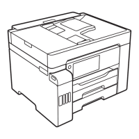
3.3.1 Board Assy (Main Board/Power Supply Board)
1. Remove the Upper Housing / Printer Cover. (p.50)
2. Remove the seven screws (four C.B.S. M3 x 6, two C.B.S. (P2) M3 x 8, and one
C.B.S. M3 x 8) that secure the Board Assy.
Figure 3-30. Removing the Board Assy (1)
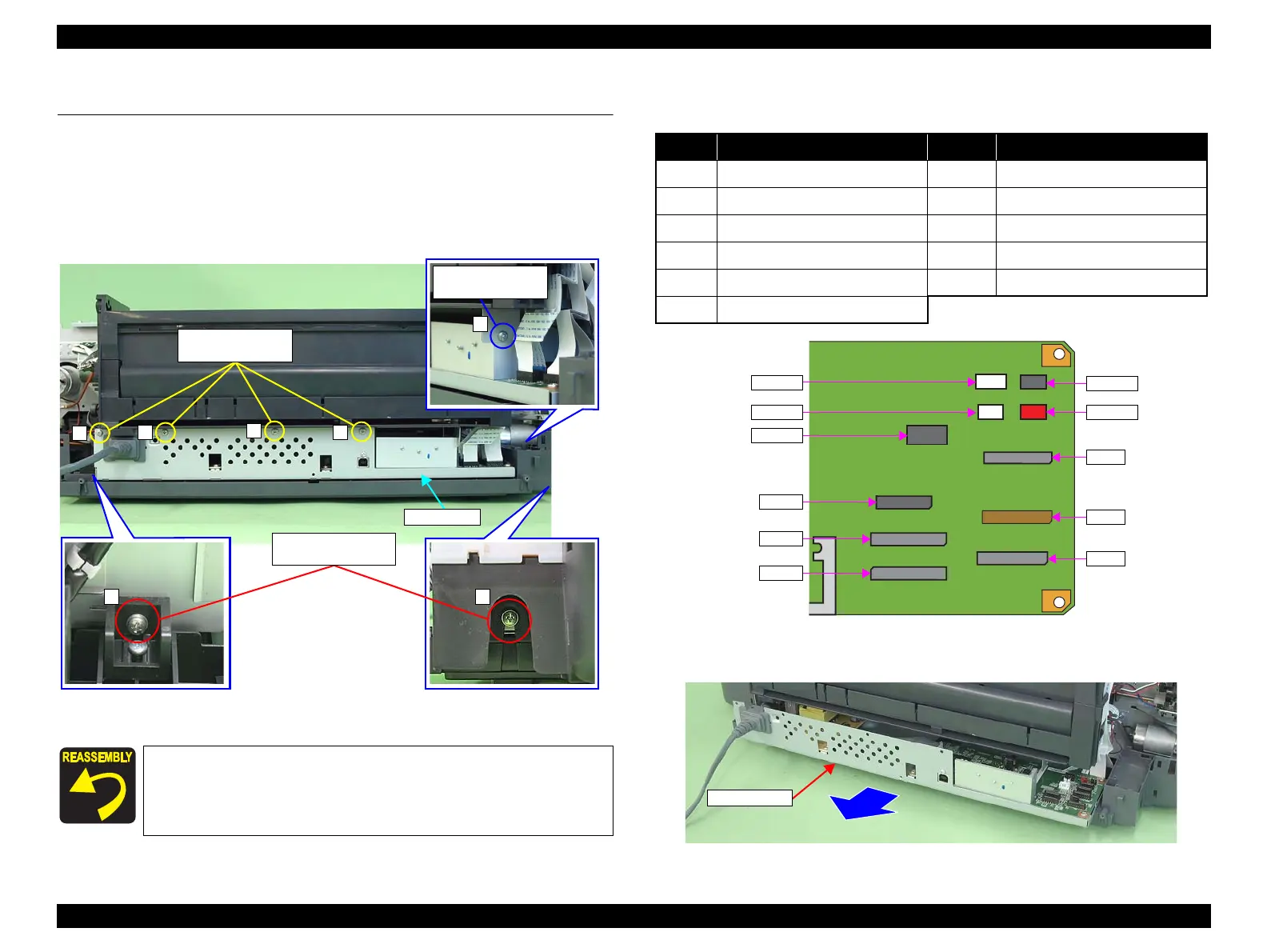
3. Disconnect all the cables and FFCs connected on the Main Board from the near
side one by one.
Figure 3-31. Connector Layout of the Main Board (130 Digit Side)
4. Pull out the Board Assy from the Printer.
Figure 3-32. Removing the Board Assy (2)
Tighten the screws in the order shown in Figure 3-30.
15) C.B.S. (P2) M3x8
(6±1 kgf.cm)
1
3
4
7
5) C.B.S. M3x8
(6±1 kgf.cm)
2) C.B.S. M3x6
(6±1 kgf.cm)
No. Connector No. Connector
CN4 Panel Board CN115 CR Motor
CN5 Relay FFC (for sensor) CN116 PF Motor
CN9 CR Encoder Sensor, PW Sensor CN117 Pump Motor
CN12 Print Head CN118 APG Motor
CN13 Print Head CN119 ASF Motor
CN14 Print Head
CN116
CN5
CN119
CN12
CN118
CN115
CN117
CN4
CN9
CN13
CN14

 Loading...