L1800 Revision A
Disassembly And Assembly Removing the Motors 95
Confidential
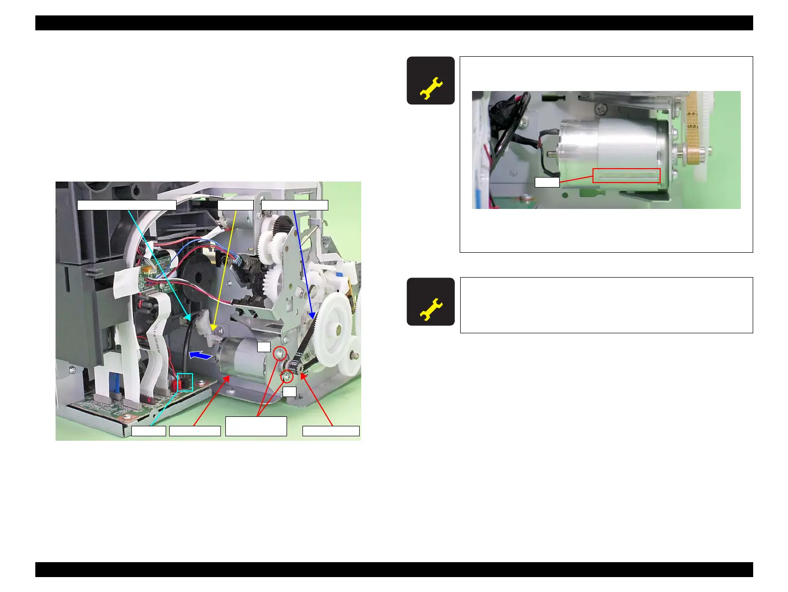
3.5.2 PF Motor
1. Remove the Printer Mechanism. (Refer to 3.4.4 Lower Housing / Printer
Mechanism (p.61).)
2. Disconnect the PF Motor connector cable from connector CN116 (black) on the
Main Board, and remove it from the Clamp on the Main Frame.
3. Remove the two C.C. M3 x 4 screws that secure the PF Motor.
4. Remove the PF Drive Belt from the PF Motor Pinion Gear, and remove the PF
Motor from the Printer Mechanism.
Figure 3-145. Removing the PF Motor
1
2
PF Motor connector cable Clamp PF Drive Belt
CN116
PF Motor
Pinion Gear
11) C.C. M3x4
(4±0.5 kgf.cm)
A D J U S T M E N T
R E Q U I R E D
Make the slit on the PF Motor face the direction shown in the
figure below.
Figure 3-146. Reinstalling the PF Motor
Tighten the screws in the order shown in Figure 3-145
A D J U S T M E N T
R E Q U I R E D
After replacing or removing the PF Motor, always make the required
adjustments referring to the following.
“Chapter 4 Adjustment (p.109)”

 Loading...