L1800 Revision A
Disassembly And Assembly Overview 43
Confidential
3.1.8 Disassembly
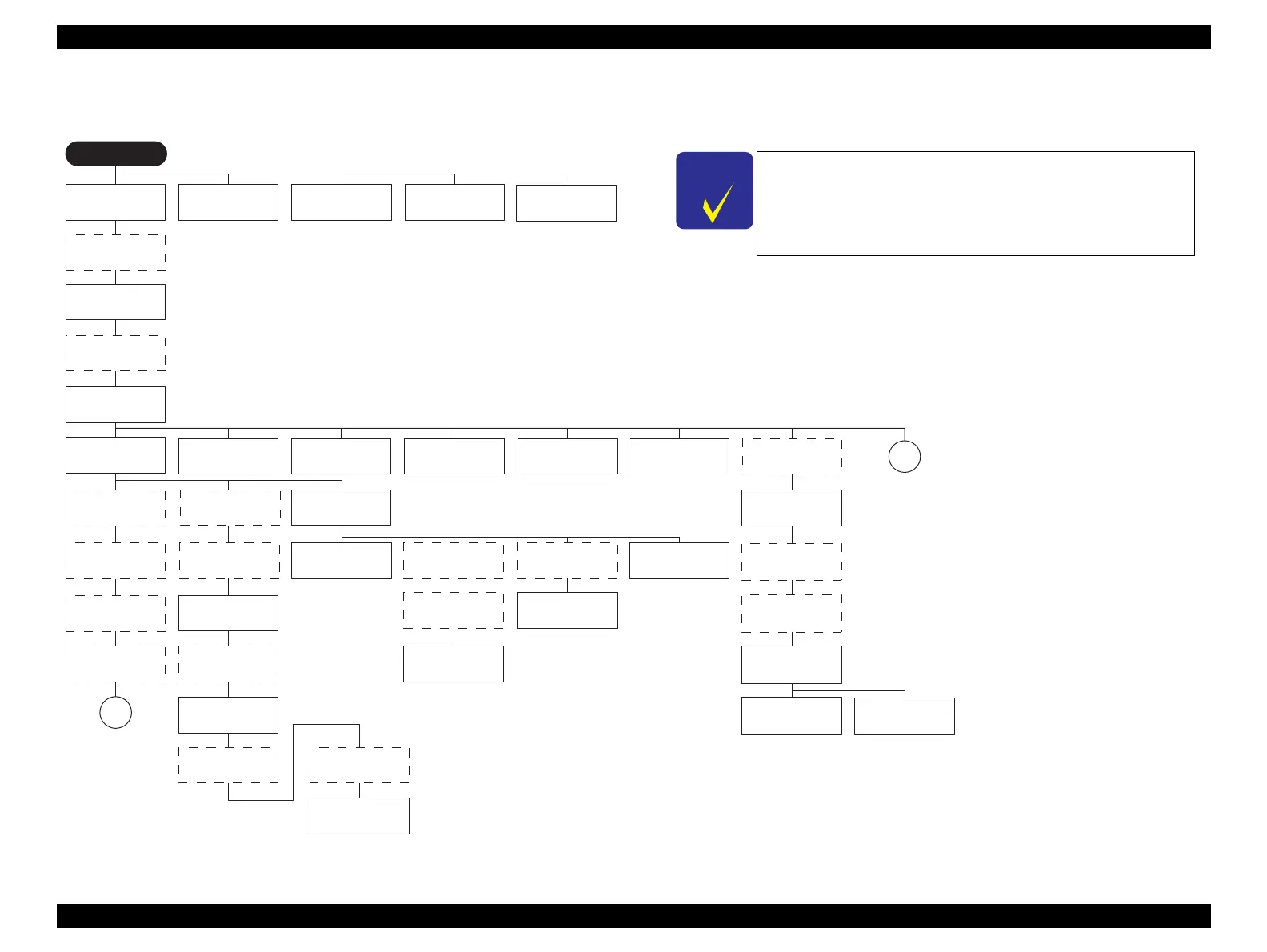
The flowchart below lists the step-by-step disassembly procedures. When disassembling each unit, refer to the page number shown in the figure.
Figure 3-11. Disassembly Flowchart (1)
Rear Housing
(p.46)
Start
Front Decoration
Plate Left/Right
(p.46)
Panel Unit (p.47)
Paper Support Assy
(p.45)
Decoration Plate
Left/Right (p.49)
Panel Unit (p.47)
Front Decoration
Plate Left/Right
(p.46)
Upper Housing /
Printer Cover
(p.50)
Upper Housing
Support Assy
(p.52)
Board Assy (Main
Board/Power Supply
Board) (p.53)
APG Assy (p.55) CR Scale (p.56)
CR Motor (p.93)
Printhead / Adapter
Guide Holder (p.58)
Ink System Unit
(p.82)
Paper EJ Frame Assy
(p.80)
PF Encoder (p.97)
Upper Paper Guide
Assys (p.91)
PF Roller Shaft
(p.88)
PW Sensor (p.98) CR Encoder (p.97)
Carriage Shaft /
Carriage Unit
(p.63)
APG Assy (p.55)
CR Scale (p.56)
ASF Motor (p.96)
Lower Housing /
Printer Mechanism
(p.61)
The boxes shown in a dotted-line are not the shortest
procedures, but are necessary to proceed to the next step.
Since a prototype was used to illustrate these disassembly
and assembly procedures, the appearance of some parts
may differ from those on an actual product.
Stacker Assy
(p.45)
PF Encoder (p.97)
ASF Assy (p.71)
ASF Motor (p.96)
LD Roller (p.74)
Retard Roller Assy
(p.76)
Paper EJ Frame Assy
(p.80)
B
A
Adapter section
(p.101)
Ink Supply Tube
Assy section
(p.102)
Ink Supply Tank
Tube Assy section
(p.104)
Ink Supply Tank
Assy section
(p.105)
Ink Supply Tube
Assy section
(p.102)
Ink Supply Tank
Tube Assy section
(p.104)
Adapter section
(p.101)
Front Paper Guide /
Paper EJ Roller (p.85)
Lower Housing /
Printer Mechanism
(p.61)

 Loading...