L1800 Revision A
Disassembly And Assembly Disassembling the Printer Mechanism 61
Confidential
3.4.4 Lower Housing / Printer Mechanism
1. Remove the Upper Housing Support Assy. (p.52)
2. Remove the Adapter section. (p.101)
3. Remove the Ink Supply Tube Assy section. (p.102)
4. Remove the Ink Supply Tank Tube Assy section. (p.104)
5. Remove the Ink Supply Tank Assy section. (p.105)
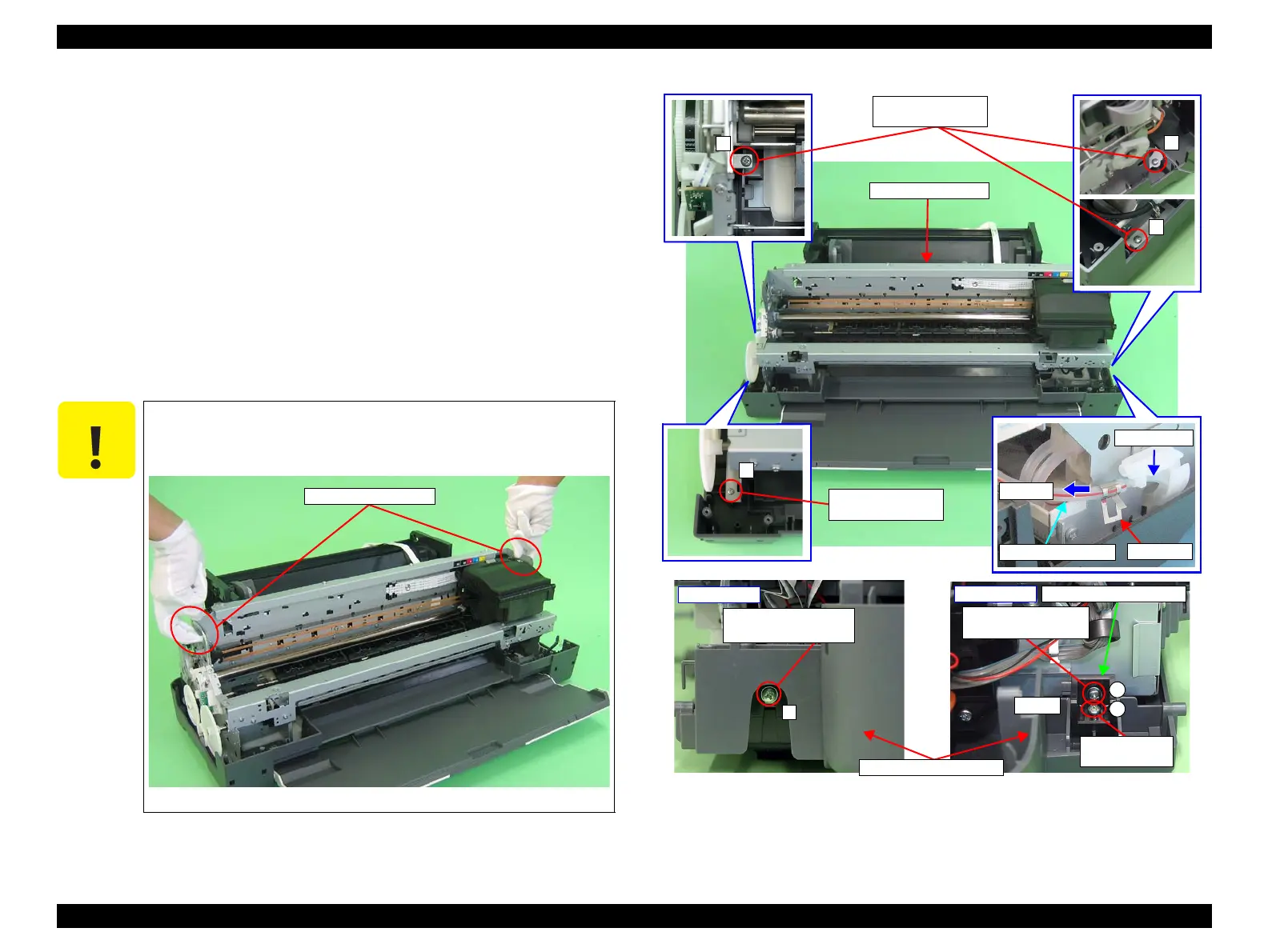
6. Grip both ends of the Ink Tube Fastener with your fingers, slide it in the direction
of the arrows, and draw out the Waste Ink Tube from the Ink Tube.
7. Remove the C.B.P. M3 x 12 screw and the C.B.S. (P2) M3 x 10 screw that secure
the Shield Plate Holder, and remove the Shield Plate Holder.
8. Remove the five screws (four C.B.P. M3 x 10 screws and one C.B.S. (P2) M3 x 10
screw) secure the Printer Mechanism.
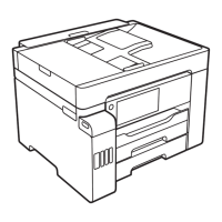
9. Lift the Printer Mechanism grasping it by the holding positions with your hands,
and remove it from the Lower Housing.
Figure 3-53. Screws that Secure the Printer Mechanism
When performing the following step, make sure to grasp the Printer
Mechanism by the specified positions shown below. Otherwise, the
frames may become deformed.
Figure 3-52. Handling the Printer Mechanism
1) C.B.P. M3x10
(6±1 kgf.cm)
Printer Mechanism
1) C.B.P. M3x10
(6±1 kgf.cm)
Step 6
Ink Tubes
Waste Ink Tubes
Fastener
5
3) C.B.S. (P2) M3x10
(6±1 kgf.cm)
Left Rear
Shield Plate Holder
18) C.B.P. 3x12
(6±1 kgf.cm)
3) C.B.S. (P2) M3x10
(6±1 kgf.cm)
Right Rear
A
B
Step 7

 Loading...