L1800 Revision A
Disassembly And Assembly Disassembling the Printer Mechanism 88
Confidential
3.4.15 PF Roller Shaft
1. Remove the Front Paper Guide / Paper EJ Roller. (p.85)
2. Remove the PF Encoder. (p.97)
3. Remove the Upper Paper Guide Assys. (p.91)
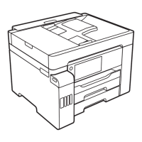
4. Loosen the two C.C. M3 x 4 screws that secure the PF Motor, and remove the PF
Drive Belt from the PF Motor Pinion Gear.
5. Remove the spacer that secures Spur Gear 31.5, and remove Spur Gear 31.5 from
the Printer Mechanism.
Figure 3-126. Removing the PF Drive Belt and Spur Gear 31.5
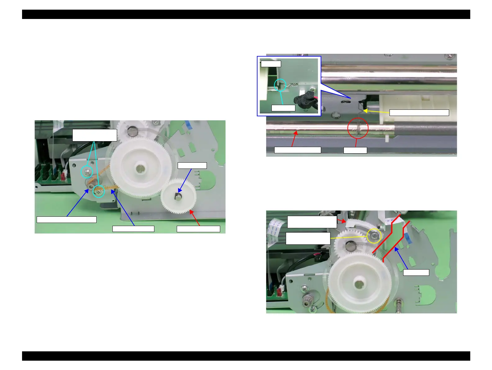
6. Remove the PG Grounding Spring from the notch on the Main Frame, and remove
the PF Grounding Spring from the groove on the PF Roller Shaft.
Figure 3-127. Removing the PF Grounding Spring
7. Make sure that the Left Parallelism Adjust Bushing is not protruding from the
notch on the Main Frame. If it is protruding, loosen the C.B.S. (P4) M3 x 8 screw
that secures the Left Parallelism Adjust Bushing, and slide it to prevent the Left
Parallelism Adjust Bushing from becoming hooked on the notch.
Figure 3-128. Rotating the Left Parallelism Adjust Bushing
PF Drive Belt
PF Motor Pinion Gear
11) C.C. M3x4
(4±0.5 kgf.cm)
Spur Gear 31.5
Spacer
Left Parallelism
Adjust Bushing
Notch
6) C.B.S. (P4) M3x8
(5±1 kgf.cm)

 Loading...