L1800 Revision A
Disassembly And Assembly Disassembling the Printer Mechanism 82
Confidential
3.4.13 Ink System Unit
1. Remove the ASF Assy. (p.71)
2.
Remove the Paper EJ Frame Assy. (p.80)
3. Remove the Lower Housing / Printer Mechanism. (p.61)
4. Release the Carriage Lock, and move the Carriage Unit to the center.
(Refer to 3.1.6
Locking/Releasing the Carriage (p.41).)
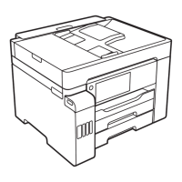
5. Release the two tabs that secure the clamps to the Upper Shield Plate, and remove
the two clamps.
6. Disconnect the Pump Motor cable from the connector CN117 on the Main Board.
7. Remove the Pump Motor cable from the Cord Keep.
Figure 3-109. Removing the Pump Motor cable
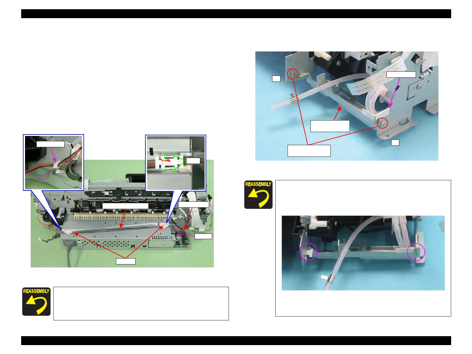
8. Remove the two C.B.S. M3 x 4 screws that secure the Ink System Guide Plate, and
remove it.
Figure 3-110. Removing the Ink System Guide Plate
Referring to Figure 3-140, attach two pieces of acetate tape to
the frame.
Referring to Figure 3-141, route the Pump Motor cable, the
Relay connector cable and the CR Motor connector cable.
CN117
Main Board
Pump Motor cable
Clamps
Align the notch on the Ink System Guide Plate with the notch
on the Main Frame.
Referring to Figure 3-110 and Figure 3-111, attach a piece of
acetate tape.
Figure 3-111. Reinstalling the Ink System Guide Plate
Tighten the screws in the order shown in Figure 3-110
1
2
10) C.B.S. M3x4
(8±1 kgf.cm)
Ink System Guide
Plate
Acetate tape

 Loading...