L1800 Revision A
Disassembly And Assembly Disassembling the Printer Mechanism 63
Confidential
3.4.5 Carriage Shaft / Carriage Unit
1. Remove the Printhead / Adapter Guide Holder. (p.58)
2. Remove the CR Scale. (p.56)
3. Remove the APG Assy. (p.55)
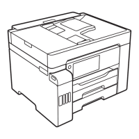
4. Rotate the PG Cam (Right) to adjust its positions other than PG++ downside.
Figure 3-57. Adjusting the PG Cam
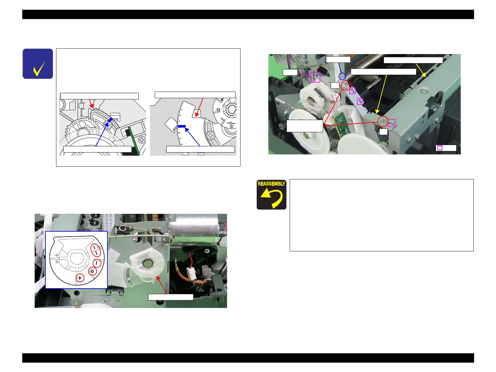
5. Remove the two C.B.S. M3 x 6 screws that secure the Frame Support Plate (Left),
and remove it.
Figure 3-58. Removing the Left Frame Support Plate
When only removing the Carriage Shaft, you do not need to
perform "4.3.2 PG Adjustment (p124)". In that case, mark the
position of the rib on the Parallelism Adjust Bushing (Left/Right)
before removing them, and make sure to align the markings with
the ribs when installing them.
Figure 3-56. Marking Position
Parallelism Adjust Bushing (Left)
Mark the position of the rib
Parallelism Adjust Bushing (Right)
Mark the position of the rib
Insert the Left Frame Support Plate into the notch on the Main
Frame. See Figure 3-58 (p.63)
Align the two tabs on the Main Frame and the tab on the Paper
EJ Frame Assy with the three positioning holes on the Frame
Support Plate (Left). See Figure 3-58 (p.63)
Align the tab (rear side) of the Left Frame Support Plate with the
outside of the Left CR Shaft Mounting Plate. See Figure 3-58
(p.63)
Tighten the screws in the order shown in Figure 3-58
1
2
2) C.B.S. M3x6
(8±1 kgf.cm)
Tab
Tabs
Left Frame Support Plate
Paper EJ Frame Assy
Notch

 Loading...