L1800 Revision A
Disassembly And Assembly Disassembling the Printer Mechanism 64
Confidential
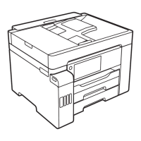
6. Remove the foot of Left PG Torsion Spring from tab A, and remove the coil
section from tab B to remove Left PG Torsion Spring from the Main Frame.
Figure 3-59. Removing the Left PG Torsion Spring
7. Remove the foot of Right PG Torsion Spring from tab A, and remove the coil
section from tab B to remove the Right PG Torsion Spring from the Main Frame.
Figure 3-60. Removing the Right PG Torsion Spring
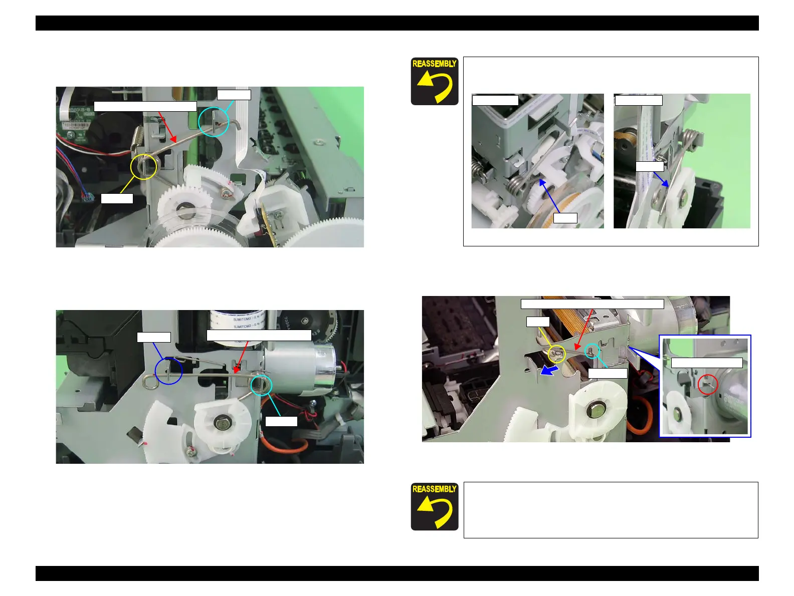
8. Remove CR Shaft Mounting Plate Fixed Spring from the tab and notch on the
Main Frame, and pull out the spring in the direction of the arrow.
Figure 3-62. Removing CR Shaft Mounting Plate Fixed Spring
Left PG Torsion Spring
Tab A
Tab B
Right PG Torsion Spring
Tab A
Tab B
Place the feet of Left PG Torsion Spring and Right PG Torsion
Spring on the Carriage Shaft.
Figure 3-61. Reinstalling PG Torsion Springs
Insert the foot of CR Shaft Mounting Plate Fixed Spring into the
notch on the Main Frame (rear side). (See Figure 3-62 (p.64))
Tab
CR Shaft Mounting Plate Fixed Spring
Notch

 Loading...