Functions 3. Installation
104 RC700 Series Rev.3
3.4.1 Typical Cable Connection
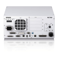
Example for Control Unit
(1) AC Power Connector
(2) M/C Power Connector
(3) M/C Signal Connector
(4) EMERGENCY Connector
(5) Development PC Connection Port
(7) LAN (Ethernet
Communication)
(8) I/O Connector
(9) TP Connector
(10) Standard RS-232C Connector
Emergency Stop
Safety Door, etc.
(12)
FieldBus I/O
Expansion I/O
RS-232C
PG board
Analog I/O EUROMAP67
Force Sensor I/F Board
Detachable connector
Cable attached at shipping
Cable prepared by users
Connector for 200VAC power input to the Controller.
The cable with connector on the Controller side.
Connect the Manipulator and the M/C POWER connector on the Controller
Insert the connectors until you hear a “click”.
The cable with connector on the Controller side.
Connect the Manipulator and the M/C SIGNAL connector on the Controller.
The EMERGENCY connector has inputs to connect the Emergency Stop switch
and the Safety Door switch. For safety reasons, connect proper switches for these
input devices.
For details, refer to the 11. EMERGENCY.

 Loading...